Supercharge Your Innovation With Domain-Expert AI Agents!

Tray locking apparatus of optical disk drive and optical disk drive adopting the same

A technology of optical disc drive and locking device, which is applied to the layout of structural components in instruments and carrier equipment, structural parts of record carriers, etc., and can solve the problems of high cost and hindering the manufacture of optical disc drives, etc.

Inactive Publication Date: 2004-01-14
TOSHIBA SAMSUNG STORAGE TECH KOREA CORP
View PDF0 Cites 1 Cited by
  • Summary
  • Abstract
  • Description
  • Claims
  • Application Information

AI Technical Summary

Problems solved by technology

However, the use of large solenoids prevents the manufacture of small optical drives and is more expensive

Method used


Image

  • Tray locking apparatus of optical disk drive and optical disk drive adopting the same
  • Tray locking apparatus of optical disk drive and optical disk drive adopting the same
  • Tray locking apparatus of optical disk drive and optical disk drive adopting the same

Examples


Embodiment Construction

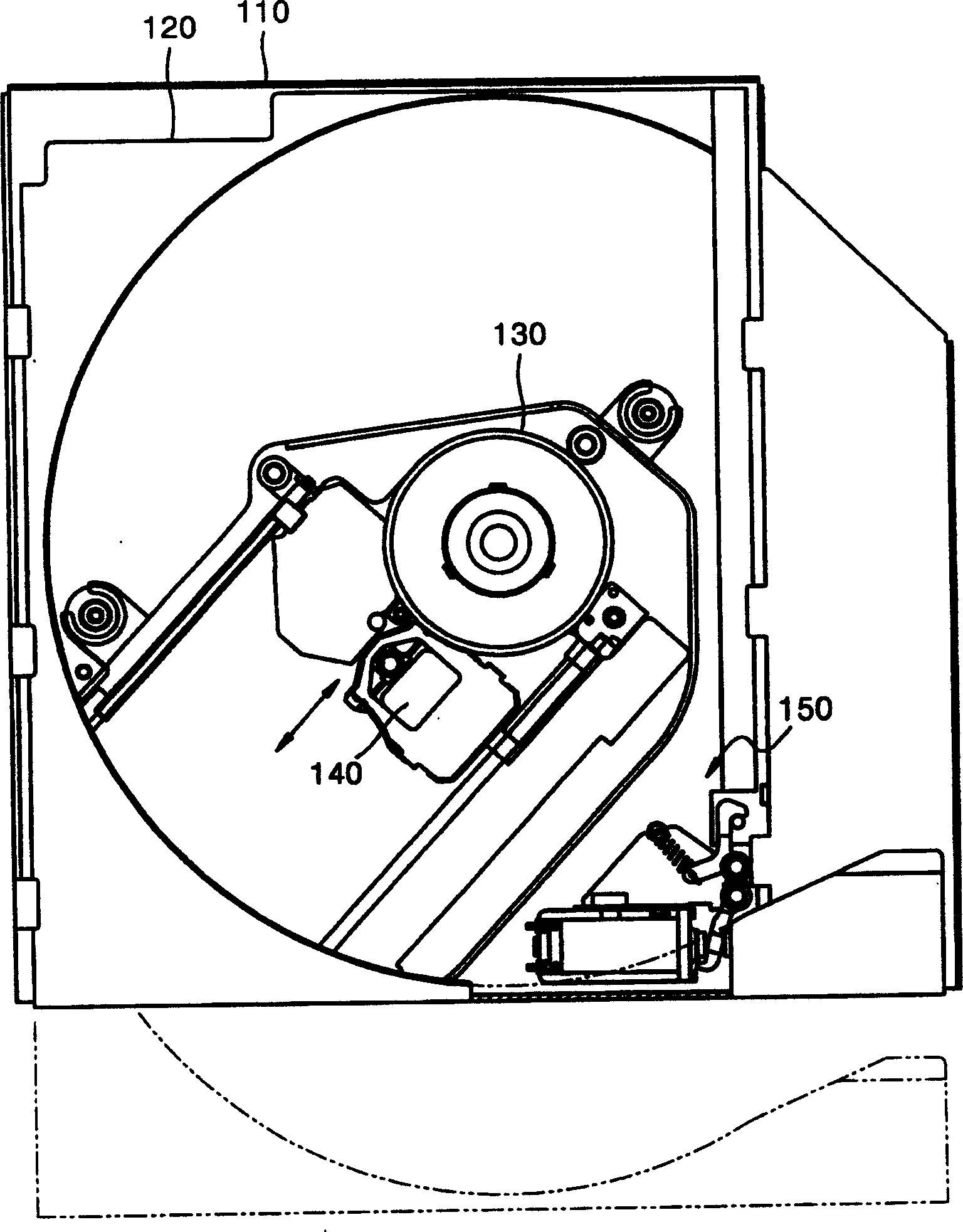
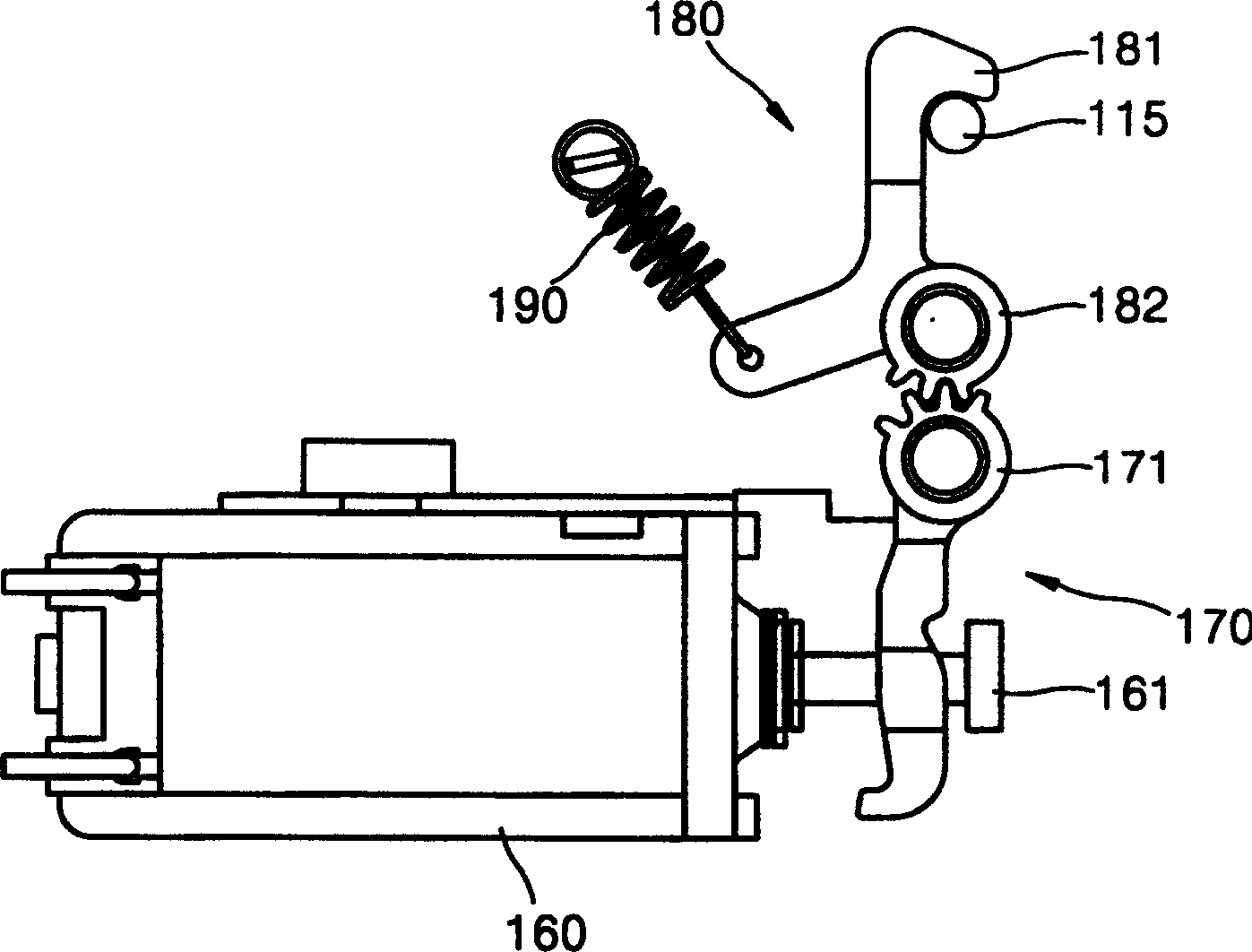
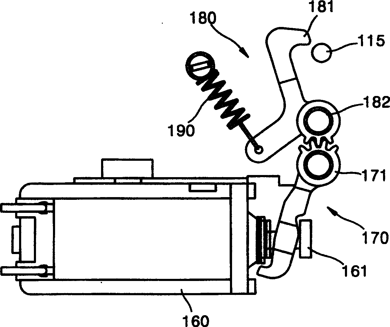
[0031] Figure 4 An optical disc drive employing a tray locking device according to a preferred embodiment of the present invention is shown. Figure 5 express Figure 4 Details of the pallet locking device shown.

[0032] refer to Figure 4 and Figure 5 , the tray 220 slides relative to the fixed frame 210 for loading and unloading. On the tray 220 are mounted a spindle motor 230 that rotates the optical disc D, and an optical pickup 240 that approaches the optical disc D. As shown in FIG. The spindle motor 230 and the optical pickup part 240 may be installed on the fixed frame 210 .

[0033] A first locking part 310 is provided on the right side of the fixing frame 210 . When the disc loading is completed, the first locking part 310 is connected with the second locking part 322 which will be described later, so as to lock the tray 220 on the fixing frame 210 . Such as Figure 4 As shown, the first locking portion 310 may be integrally formed with the fixing frame 26...


PUM


Abstract

A tray locking apparatus of an optical disk drive including a fixed frame and a tray that moves in and out of the fixed frame to load and unload a disk. The tray locking apparatus includes a first locking portion provided on the fixed frame, and a first lever, that has a second locking portion selectively coupled to the first locking portion, and moves between a coupling position and a releasing position. A first elastic member biases the first lever in a direction toward the coupling position. A switching unit installed at the tray locks the first lever at the coupling position by a magnetic force, and unlocks and moves the first lever to the releasing position by temporarily offsetting the magnetic force. A returning unit makes the first lever return to the coupling position from the releasing position when the tray moves out of the fixed frame.

Description

[0001] This application claims priority to Hanwei Patent Application No. 2002-39152 filed on July 6, 2002 at the Korean Intellectual Property Office. This patent application is hereby incorporated by reference in its entirety. technical field [0002] The present invention relates to an optical disc drive, and more particularly, to a tray locking device made slim so as to be used in a slim optical disc drive and an optical disc drive using the tray locking device. Background technique [0003] Generally, an optical disc drive records information on a disc-shaped medium such as a compact disc CD or a digital video disc DVD, or reproduces information from these discs. The tray on which the disc is mounted fits into the optical drive and slides in and out of the drive body. In particular, unlike a tray for a typical optical drive that is loaded or unloaded by an additional loading motor, since a tray mounted on a slim optical drive for a notebook computer mainly has manual sli...

Claims


Application Information

Patent Timeline
Patent Type & Authority Applications(China)
IPC IPC(8): G11B17/04G11B33/12
CPCG11B33/121G11B17/04
Inventor 安哲雄
Owner TOSHIBA SAMSUNG STORAGE TECH KOREA CORP
Features
  • R&D
  • Intellectual Property
  • Life Sciences
  • Materials
  • Tech Scout
  • Unparalleled Data Quality
  • Higher Quality Content
  • 60% Fewer Hallucinations
Learn More