Mechanism for the deployment of endovascular implants

A technique for laying tubes and internal devices, which is applied in the field of embolizing vascular aneurysms and similar vascular abnormalities, and achieves the effects of easy repositioning, easy adaptation, and convenient and reliable separation

Inactive Publication Date: 2004-01-21
MICROVENTION INC
View PDF28 Cites 29 Cited by
  • Summary
  • Abstract
  • Description
  • Claims
  • Application Information

AI Technical Summary

Problems solved by technology

However, like the conventional microcoil technique, the success of GDC is largely limited to small aneurysms with narrow necks.

Method used


Image

  • Mechanism for the deployment of endovascular implants
  • Mechanism for the deployment of endovascular implants
  • Mechanism for the deployment of endovascular implants

Examples


Embodiment Construction

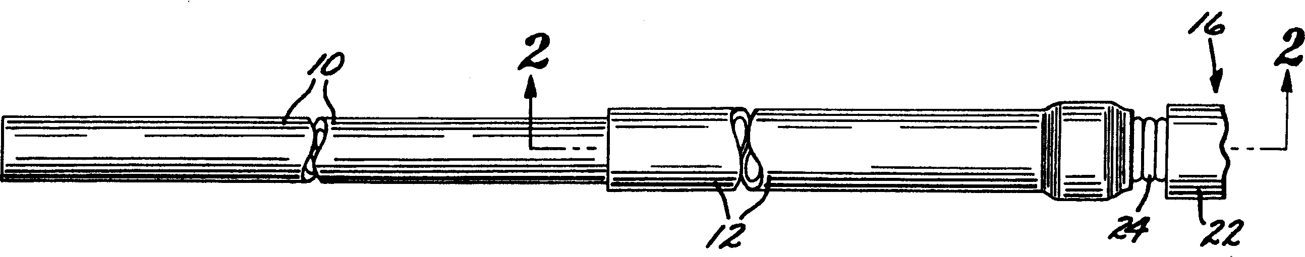
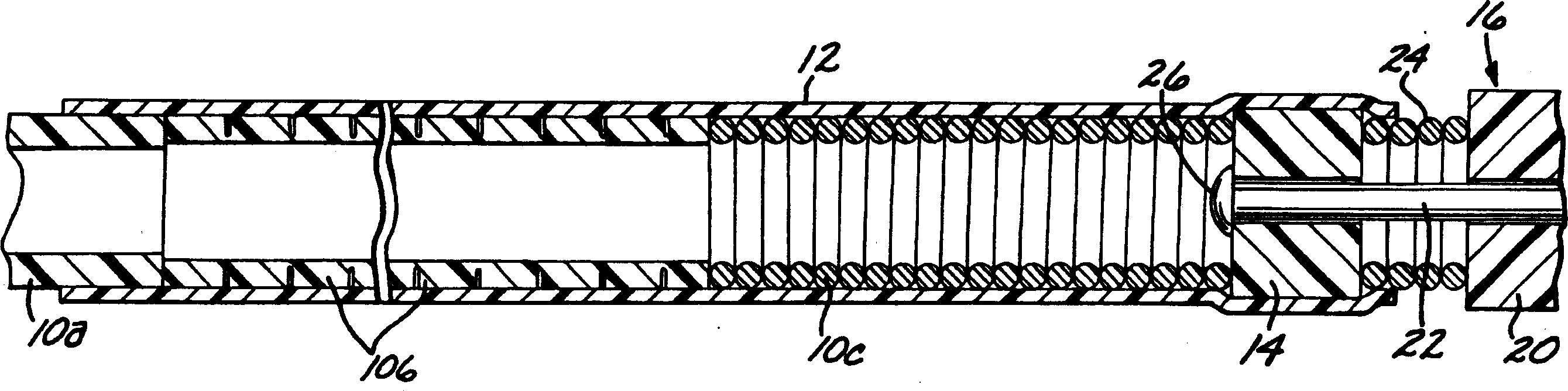
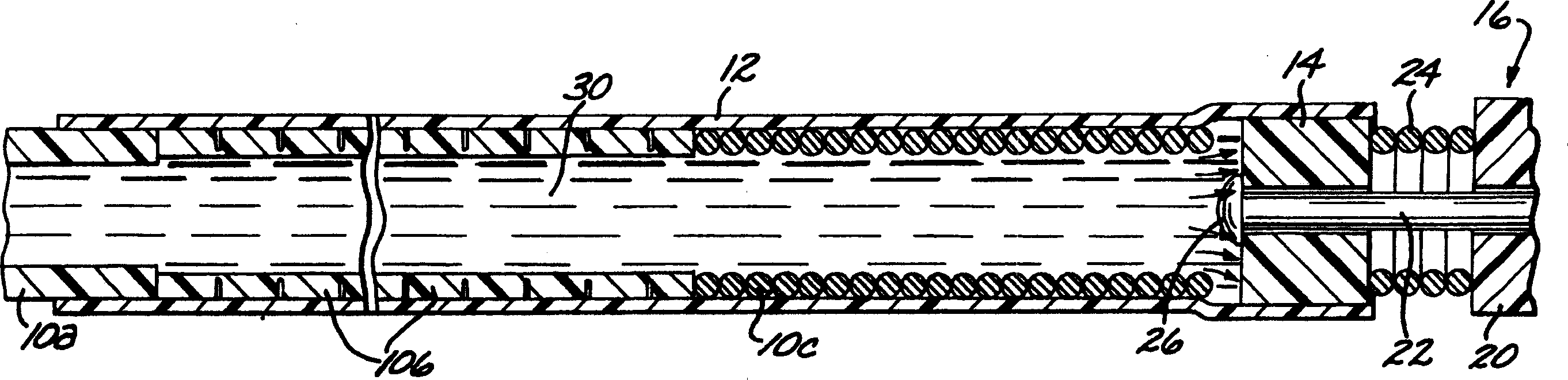
[0040] first reference figure 1 According to the present invention, a deployment device for an intravascular device comprises an elongated flexible hollow deployment tube 10 having an open proximal end 11 (see Figure 11 ) and end at the distal portion of the open distal end 13, with a continuous fluid passage cavity 15 formed between the proximal and distal ends. A retention sleeve 12 is fixed around the deployment pipe 10, said retention sleeve comprising a terminal extension 17 which extends a short distance past the distal end 13 of the deployment pipe. The deployment device also includes a connector 14 secured to the proximal end (only the proximal end of which is shown) of a filamentary intravascular device 16, which may be, for example, an embolic implant.

[0041] The deployment tube 10 is fabricated from stainless steel and is preferably formed in three sections, each sized to pass through a typical microcatheter. The proximal or main section 10a is the longest sect...


PUM


Abstract

A mechanism for the deployment of a filamentous endovascular device includes an elongate, flexible, hollow deployment tube having an open proximal end, and a coupling element attached to the proximal end of the endovascular device. The deployment tube includes a distal section terminating in an open distal end, with a lumen defined between the proximal and distal ends. A retention sleeve is fixed around the distal section and includes a distal extension extending a short distance past the distal end of the deployment tube. The endovascular device is attached to the distal end of the deployment tube during the manufacturing process by fixing the retention sleeve around the coupling element, so that the coupling element is releasably held within the distal extension of the deployment tube. In use, the deployment tube, with the implant attached to its distal end, is passed through a microcatheter to a target vascular site until the endovascular device is deployed within the site. To detach the endovascular device from the deployment tube, a biocompatible liquid is injected through the lumen of the deployment tube so as to apply pressure to the upstream side of the coupling element, which is thus pushed out of the retention sleeve by the fluid pressure, thereby detaching the endovascular device from the deployment tube. The coupling element may be a solid 'plug' of polymeric material or metal, or it may be formed of a hydrophilic polymer that softens and becomes somewhat lubricious when contacted by the injected liquid. With the latter type of material, the hydration of the hydrophilic material results in physical changes that reduce the adhesion between the coupling element and the sleeve. Alternatively, the coupling element can be made principally of a non-hydrophilic material, with a hydrophilic coating.

Description

[0001] Cross References to Related Applications technical field [0002] The present invention relates to the field of methods and devices for embolizing vascular aneurysms and similar vascular abnormalities. In particular, the present invention relates to a device for deploying an implant, such as a microcoil, within a target vascular site and then loosening or detaching the implant within the lesion. Background technique [0003] Embolization of blood vessels is required in many clinical conditions. For example, vascular embolization has been used to control vascular bleeding, to occlude blood supply to tumors, and to occlude aneurysms, especially intracranial aneurysms. In recent years, embolization of blood vessels for the treatment of aneurysms has received attention. Several different treatment methods have been used in the prior art. For example, US Pat. No. 4,819,637 to Domandy, Jr. et al. discloses a vascular embolization system using a detachable balloon deliver...

Claims


Application Information

Patent Timeline
Patent Type & Authority Applications(China)
IPC IPC(8): A61B17/00A61B17/12A61F2/06
CPCA61B17/12022A61B17/1214A61B17/12163A61B2017/00539A61B2017/00535A61B2017/00867A61B17/1215A61B2017/12054A61B2017/1205A61B17/1219A61B2017/00477
Inventor 戴维·A·费雷拉乔治·R·小格林布里安·J·考克斯罗伯特·F·罗森布卢特
Owner MICROVENTION INC
Why Eureka
Try Eureka