

Three-coordinate koniogravimeter
A technology of a three-coordinate measuring instrument and a cylindrical coordinate system, applied in the field of measurement, can solve the problems of a large structure and high price of a three-coordinate measuring instrument, and achieve the effects of low cost, light structure, and simple and easy operation.
- Summary
- Abstract
- Description
- Claims
- Application Information
AI Technical Summary
Problems solved by technology
Method used
Image

Examples
Embodiment Construction
[0016] In specific implementation:
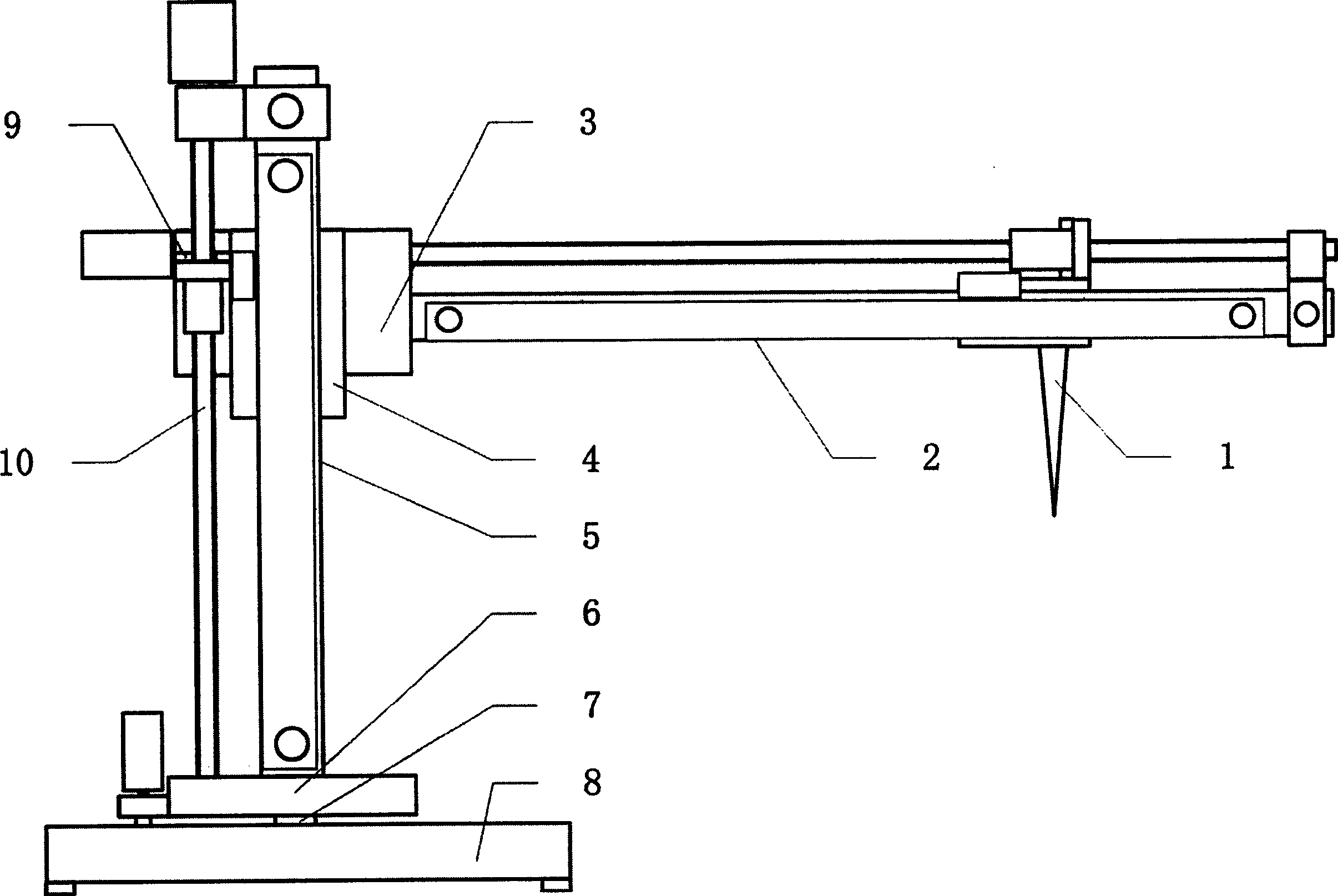
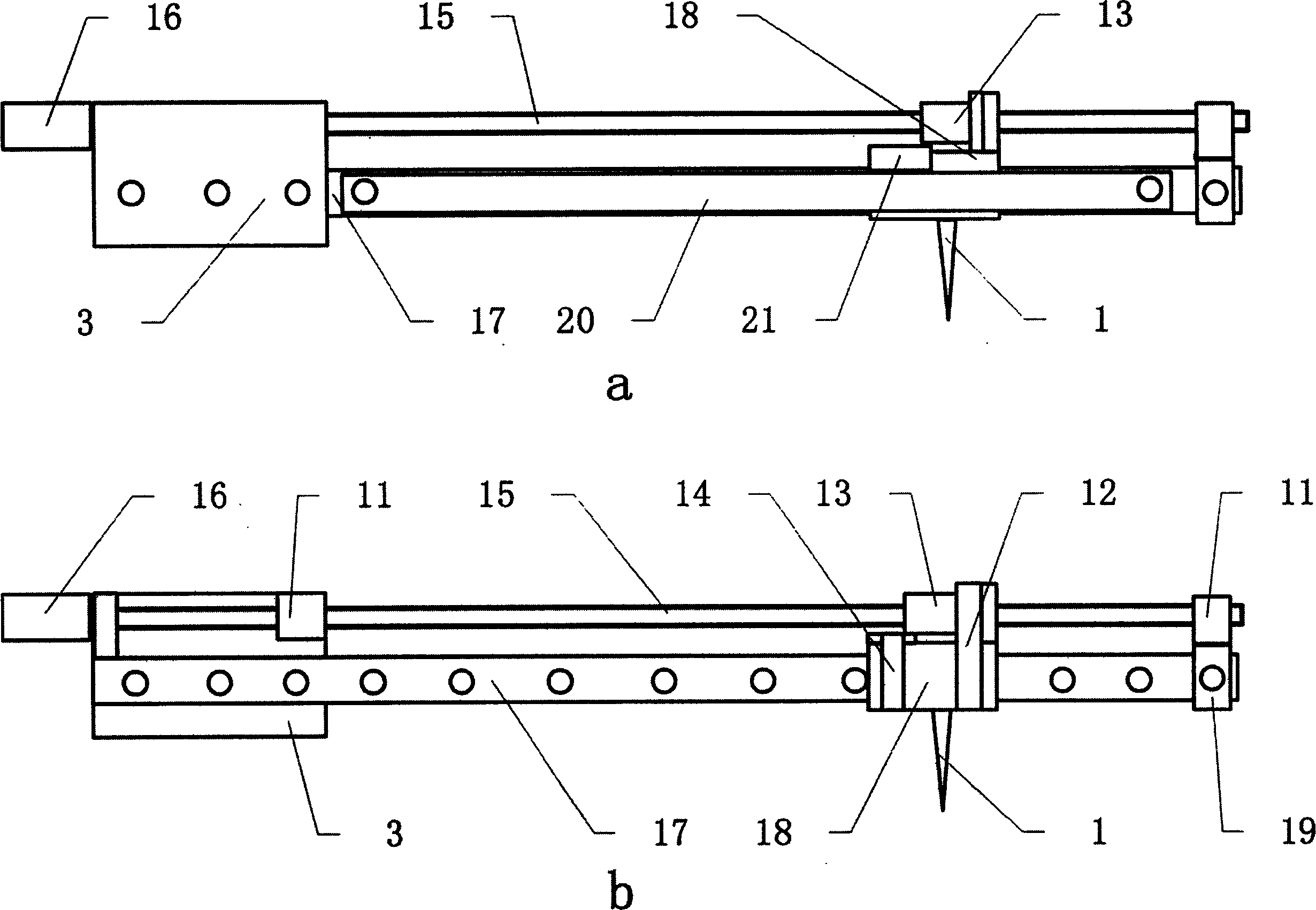
[0017] The first step is to make the cross arm 2 mainly composed of the measuring probe 1 , the fixed plate 3 , the driving screw 15 , the slide rail 17 , the motor 16 and the linear displacement sensor 20 .
[0018] The fixed plate 3 is located at one end of the cross arm and is made of steel, the basic shape is square, and the upper surface is stepped, such as Figure 5 As shown, there are slide rail mounting holes 34, slider mounting holes 35, folding plate mounting holes 36, motor mounting holes, and bearing mounting holes on the fixed plate 3. Fixed block 19 is positioned at cross arm other end, and is made of steel, and basic shape is cube, and the four jiaos of upper surface have the screw hole that bearing is installed, and side center has square through hole, and through hole size is identical with slide rail 17 profiles. On the fixed plate 3 and the fixed block 19, there are respectively screw-fixed bearings 11 in order to instal...
PUM
 Abstract
Description
Claims
Application Information