Flow metering device
A technology of flow measurement and flow, which is applied in measuring devices, measuring flow/mass flow, liquid/fluid solid measurement, etc. It can solve the problems of easy adjustment error, time-consuming reference voltage setting, etc., and achieve high measurement accuracy. Effect
- Summary
- Abstract
- Description
- Claims
- Application Information
AI Technical Summary
Problems solved by technology
Method used
Image

Examples
Embodiment 1
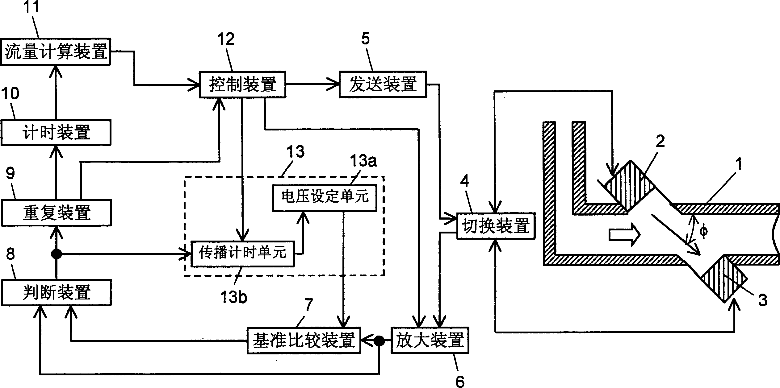
[0032] figure 1 It is a block diagram of the flow metering device in Embodiment 1 of the present invention, figure 2A schematic diagram illustrating the operation of a flow metering device. A first ultrasonic oscillator 2 for emitting ultrasonic waves and a second ultrasonic oscillator 3 for receiving ultrasonic waves are arranged in the middle of the flow path 1 through which the fluid flows, and they are arranged to form an angle φ with the flow direction of the fluid. The transmitting device 5 drives the first ultrasonic oscillator 2 or the second ultrasonic oscillator 3 to emit ultrasonic waves. The switching device 4 switches the ultrasonic transmitting / receiving operations performed in the first ultrasonic oscillator 2 and the second ultrasonic oscillator 3 . The gain of the amplifying device 6 is adjusted so that the signal received by the ultrasonic oscillator on the receiving side is output at a constant amplitude. The reference setting means 13 sends the referen...
Embodiment 2
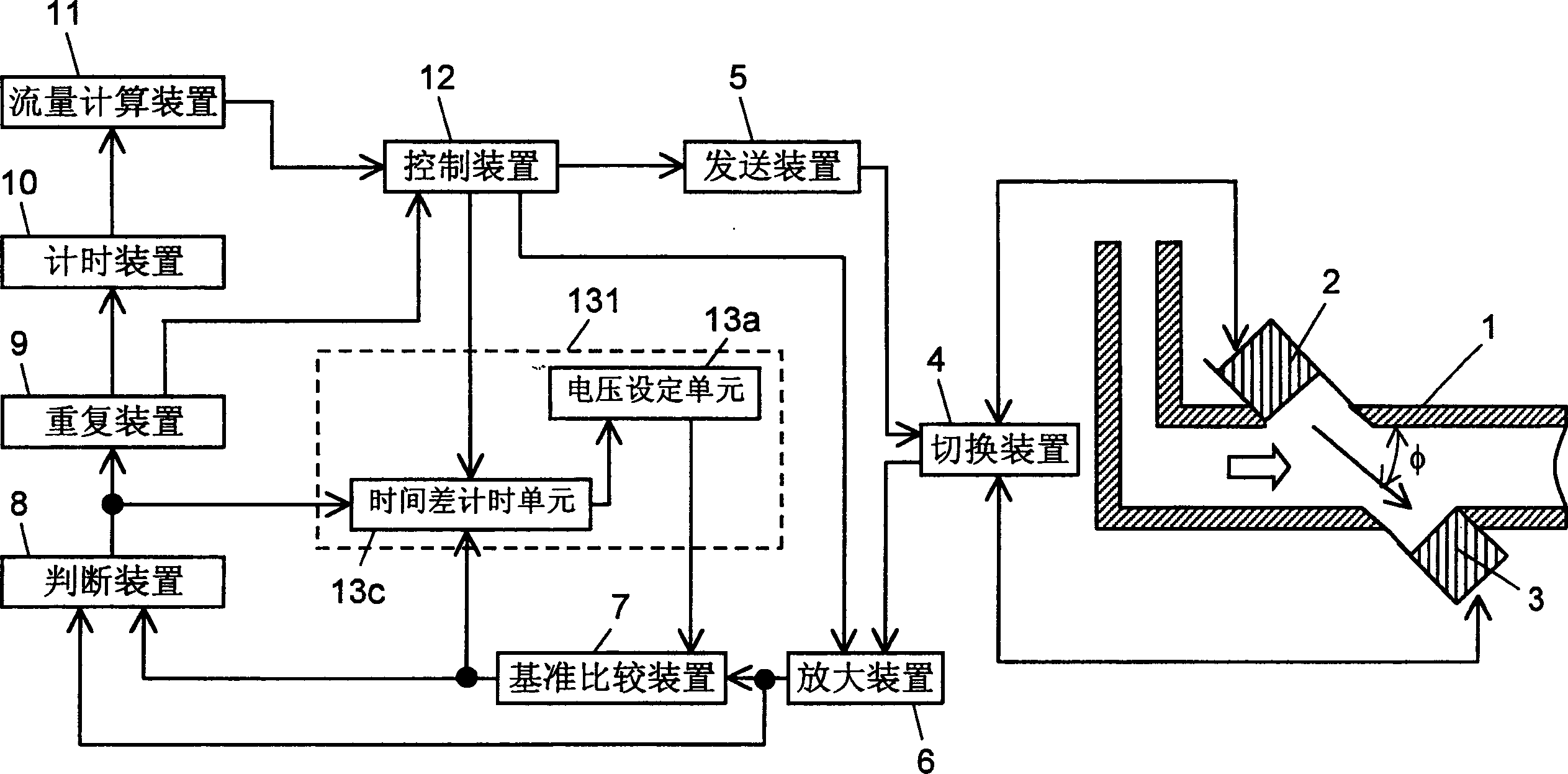
[0041] image 3 It is a block diagram of the flow metering device in Embodiment 2 of the present invention, Figure 4 and Figure 5 A schematic diagram illustrating the operation of the flow metering device. The time difference counting unit 13 c counts the time difference between the output of the reference comparing means 7 and the output of the judging means 8 . The voltage setting unit 13 a sets a reference voltage according to the output of the time difference timer unit 13 c, and outputs the set voltage to the reference comparison device 7 . The voltage setting unit 13 a and the time difference timer unit 13 c constitute a reference setting device 131 . Since the other components are the same as in Embodiment 1, description thereof will be omitted.
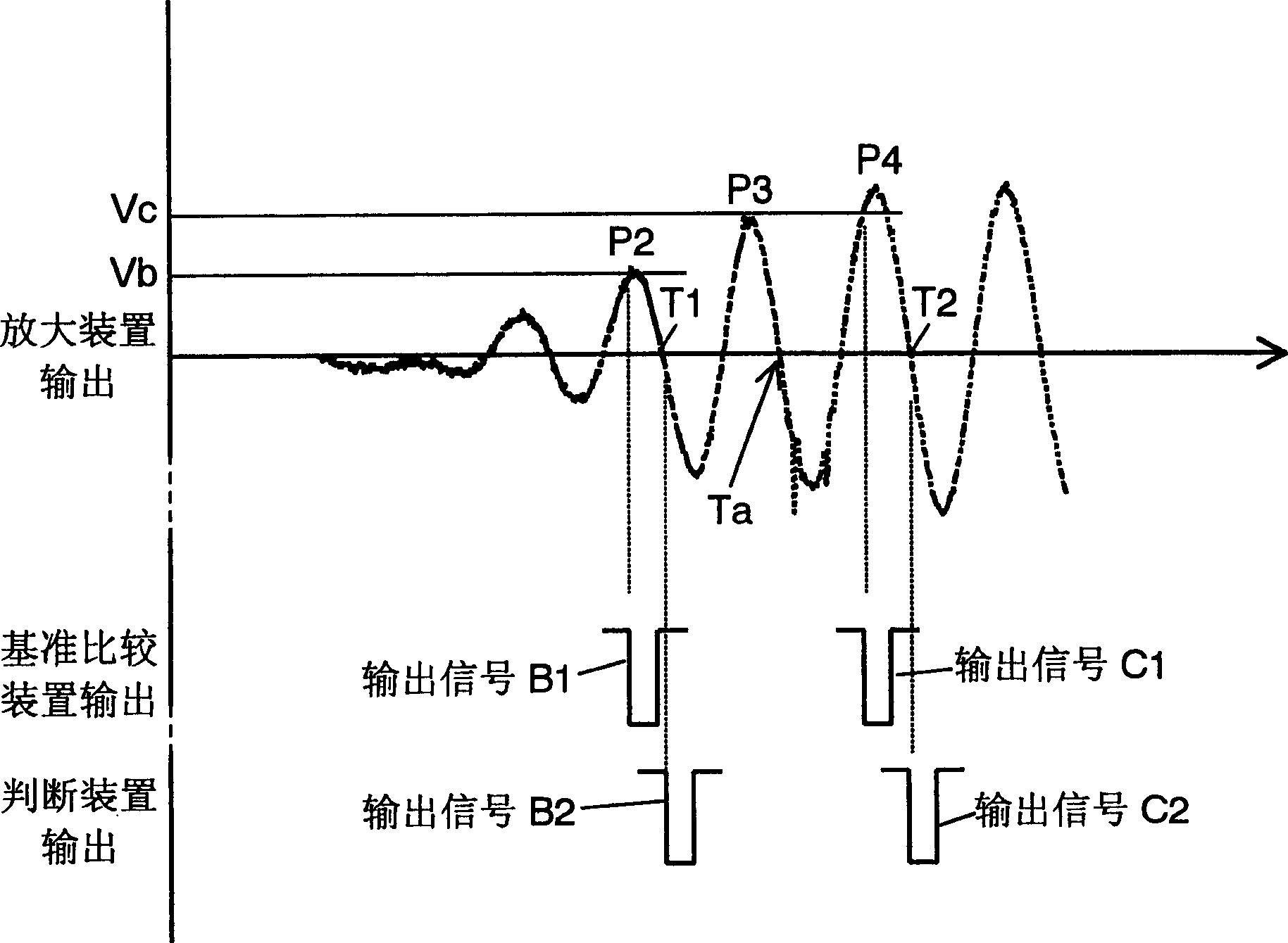
[0042] Next, the operation of the flow measuring device having the above construction will be described. When flow measurement is started, the control device 12 operates the transmitter 5 to emit ultrasonic waves from t...
Embodiment 3
[0047] Figure 6 It is a block diagram of the flow measuring device in Embodiment 3 of the present invention. Figure 7 is a schematic diagram illustrating the operation of the flow metering device, Figure 8 is a flowchart showing its operation. A first ultrasonic oscillator 2 and a second ultrasonic oscillator 3 for transmitting / receiving ultrasonic waves are arranged at a certain angle φ relative to the flow direction of the fluid on the flow path 1 . The transmitter 5 causes the first ultrasonic oscillator 2 or the second ultrasonic oscillator 3 to emit ultrasonic waves. The switching device 4 is used for exchanging the ultrasonic transmitting / receiving operations in the first ultrasonic oscillator 2 and the second ultrasonic oscillator 3 . The amplifying device 6 amplifies the signal received by the ultrasonic oscillator on the receiving side according to the gain controlled by the control device 12 , and the reference comparing device 7 compares the signal amplified b...
PUM
 Abstract
Description
Claims
Application Information
 - R&D
- Intellectual Property
- Life Sciences
- Materials
- Tech Scout
- Unparalleled Data Quality
- Higher Quality Content
- 60% Fewer Hallucinations
Browse by: Latest US Patents, China's latest patents, Technical Efficacy Thesaurus, Application Domain, Technology Topic, Popular Technical Reports.
© 2025 PatSnap. All rights reserved.Legal|Privacy policy|Modern Slavery Act Transparency Statement|Sitemap|About US| Contact US: help@patsnap.com