Cutting tip monitoring device for cutting device

A technology for cutting inserts and cutting devices, which is applied to measuring/indicating equipment, electrical components, circuits, etc., and can solve problems such as difficulty in applying multiple inserts, and inability to correctly detect cutting edge states and changes of cutting inserts.

Active Publication Date: 2004-02-25
DISCO CORP
View PDF0 Cites 9 Cited by
  • Summary
  • Abstract
  • Description
  • Claims
  • Application Information

AI Technical Summary

Problems solved by technology

[0005] (1) Due to the influence of cutting water, light is refracted, and although there is no damage to the cutting edge, it may be misjudged that damage has occurred
[0006] (2) If dirt generated by cutting adheres to the light-emitting surface of the light-emitting element or the light-receiving surface of the light-receiving element, the amount of light received by the light-receiving element will change, so the state of the cutting edge of the cutting blade cannot be accurately detected
[0007] (3) Since the light-emitting element and the light-receiving element are arranged so as to sandwich the cutting edge of the cutting insert, it is difficult to apply to the so-called multi-blade case in which two or more cutting inserts are arranged in the axial direction.

Method used


Image

  • Cutting tip monitoring device for cutting device
  • Cutting tip monitoring device for cutting device
  • Cutting tip monitoring device for cutting device

Examples


Embodiment Construction

[0063] The following details the cutting blade monitoring device of the cutting device according to the present invention with reference to the accompanying drawings.

[0064] preferred embodiment.

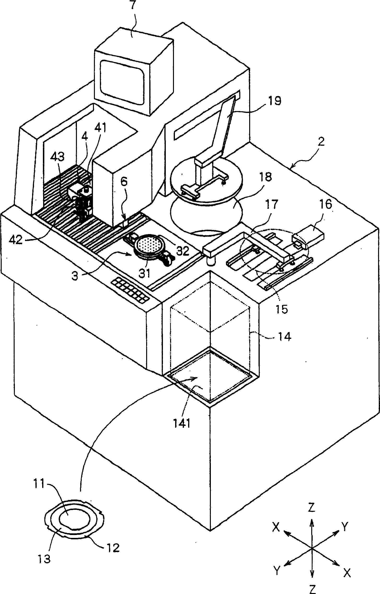
[0065] figure 1 It is a perspective view showing a cutting device equipped with a cutting blade monitoring device according to the present invention.

[0066] The cutting device in the illustrated embodiment includes a substantially rectangular parallelepiped device stand 2 . In the apparatus stand 2, a chuck table 3 serving as a workpiece holding unit for holding a workpiece is arranged so as to be movable in a direction indicated by an arrow X which is a cutting feed direction. The chuck table 3 is provided with: an adsorption chuck support table 31, and an adsorption chuck 32 mounted on the adsorption chuck support table 31, and a workpiece to be processed, such as a disk-shaped semiconductor wafer, is held on the adsorption chuck 32 by an adsorption device not shown in the f...


PUM


Abstract

Provided is a cutting blade monitoring device for a cutting device capable of correctly detecting the state of a cutting edge of a cutting blade without being affected by cutting water or contamination, which can also be applied to cutting devices having multiple blades. This cutting blade monitoring device is for a cutting device provided with a workpiece holding means to hold a workpiece, and a cutting means to cut the workpiece held by the workpiece holding means, where the cutting means is provided with a rotary spindle, and a cutting blade installed on the rotary spindle, and provided with a cutting edge comprising abrasive grains fixed by magnetic material. It is provided with a magnetism sensor disposed to face the outer circumference of the cutting edge of the cutting blade, and a control means to determine the state of the cutting edge based on detection signals from the magnetism sensor.

Description

【Technical field】 [0001] The present invention relates to a cutting blade monitoring device of a cutting device, and more specifically, to a cutting blade monitoring device of a cutting device for determining the breakage and wear limit of a cutting blade for cutting workpieces such as semiconductor wafers. 【Background technique】 [0002] As is well known to those skilled in the art, in a semiconductor device manufacturing process, the surface of a generally wafer-shaped semiconductor wafer is divided into a plurality of regions by lines (cutting lines) arranged in a grid. Circuits such as ICs and LSIs are formed in this divided area. Then, by cutting the semiconductor wafer along the lanes, the regions where the circuits are formed are separated, and individual semiconductor chips are manufactured. Typically, semiconductor wafers are severed along the lanes using a cutting device known as a slicer. This cutting device includes: a chuck table as a workpiece holding unit th...

Claims


Application Information

Patent Timeline
IPC IPC(8): B23Q17/09B23Q17/00H01L21/301
Inventor 森本贺津美松原政幸菅野洋平
Owner DISCO CORP
Why Eureka
Try Eureka