System and method for repairing composite parts

a composite and repair method technology, applied in the field of composite parts system and method, can solve the problems of composite parts being difficult to replace, composite parts can be difficult to manufacture, and composite parts can be difficult to replace, etc., and achieve the effect of improving the repair efficiency and time-saving

Active Publication Date: 2008-11-13
SPIRIT AEROSYSTEMS
View PDF8 Cites 70 Cited by
  • Summary
  • Abstract
  • Description
  • Claims
  • Application Information

AI Technical Summary

Benefits of technology

[0010]Some embodiments of the invention may also comprise a numerical control (NC) machine for receiving the map from the computing device to manufacture the plurality of filler plies for filling the space inward of the composite ply edges. The NC machine may manufacture each filler ply with a peripheral edge shaped such that it corresponds with the ply edge of one ply of

Problems solved by technology

However, composite components can be expensive and time-consuming to manufacture, so it is not always cost-effective to replace a composite part when it is damaged.
This repair method can

Method used


Image

  • System and method for repairing composite parts
  • System and method for repairing composite parts
  • System and method for repairing composite parts

Examples


Embodiment Construction

[0020]The following detailed description of the invention references the accompanying drawing figures that illustrate specific embodiments in which the present invention can be practiced. The embodiments are intended to describe aspects of the invention in sufficient detail to enable those skilled in the art to practice the invention. Other embodiments can be utilized and changes can be made without departing from the scope of the present invention. The following detailed description is, therefore, not to be taken in a limiting sense.

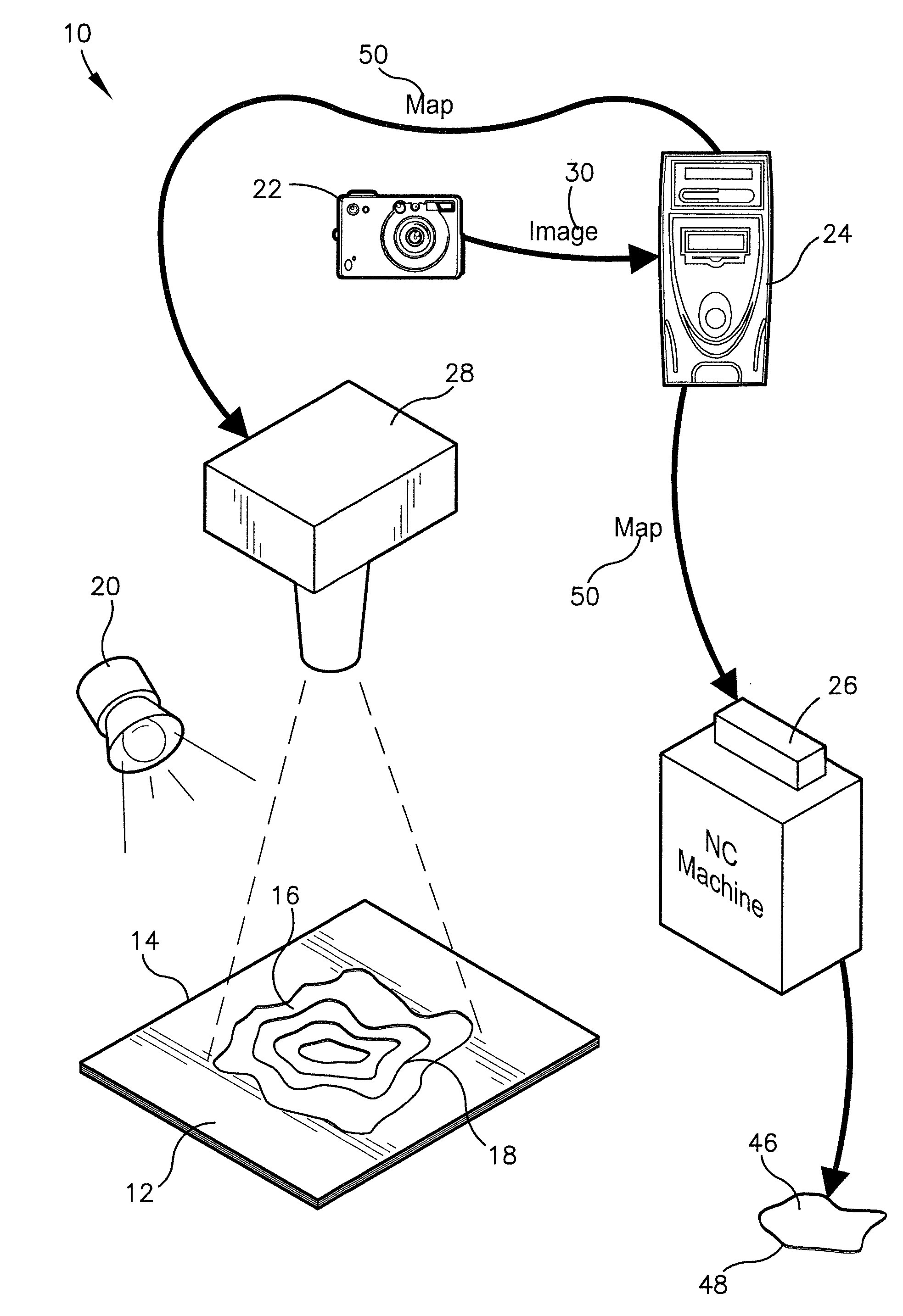
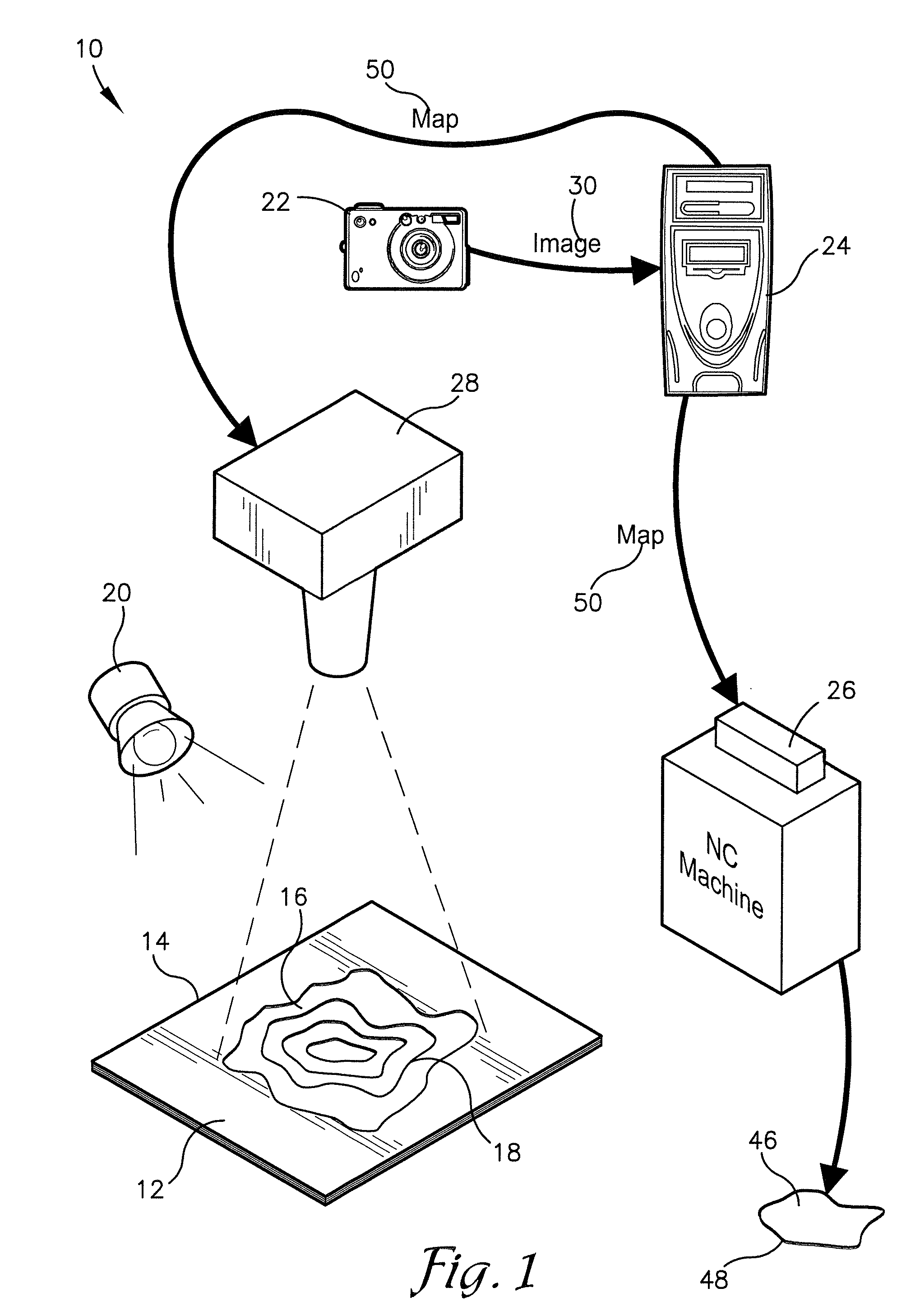
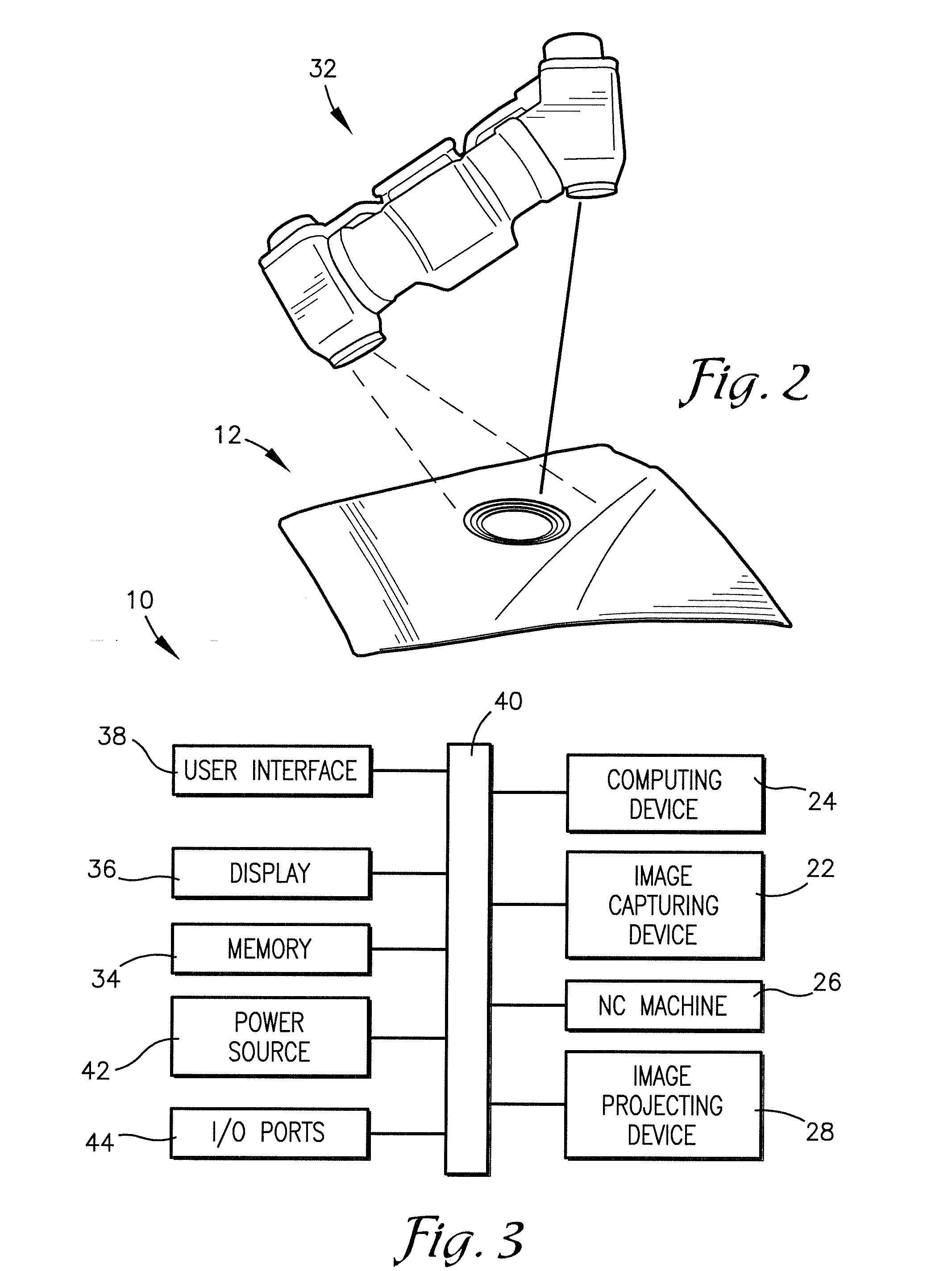
[0021]Embodiments of the present invention, as illustrated in FIG. 1, provide a composite repair system 10 for assisting in the repair of a composite part 12 having a peripheral edge 14 and a plurality of cured composite plies 16, each having a ply boundary 18, also referred to herein as a ply edge. The composite repair system 10 may comprise a light source 20, an image capturing device 22, a computing device 24, a numerical control (NC) machine 26, and...


PUM

PropertyMeasurementUnit
Reflectionaaaaaaaaaa

Abstract

A composite repair system and method for assisting in the repair of a cured composite part in which a damaged portion has been cut out and removed, exposing a plurality of composite plies and their corresponding composite ply edges. The composite repair system may comprise a light source to illuminate the ply edges, an image capturing device to obtain an image of the ply edges, and a computing device for processing the image of the ply edges and creating a map of the ply edges based on the image. The map may be used to manufacture filler plies having peripheral edges shaped to correspond with the composite ply edges for replacing the damaged portion of the composite part.

Description

RELATED APPLICATIONS[0001]This nonprovisional patent application claims priority benefit, with regard to all common subject matter, of earlier-filed U.S. provisional patent application titled “Automated Composite Repair Using Three-Dimensional Metrology Equipment”, Ser. No. 60 / 916,700, filed May 8, 2007. The identified earlier-filed application is hereby incorporated by reference in its entirety into the present application.BACKGROUND[0002]1. Field[0003]Embodiments of the present invention relate to a system and method for repairing composite parts, such as aircraft parts and the like. More particularly, the invention relates to a system and method for creating a map of a plurality of composite ply edges. The map may be used for manufacturing and applying filler composite plies to the ply edges of the composite part, replacing a removed damaged portion of the composite part.[0004]2. Related Art[0005]Composite parts for use in airplanes and other applications may be made from strips ...

Claims


Application Information

Patent Timeline
IPC IPC(8): G06F15/00G06K9/03G05B19/18
CPCB29C73/06B29C73/10B29C73/24G01B11/2531G05B19/401G05B19/18G06F15/00G06V10/98
Inventor CORK, GLEN PAULBORGMAN, MICHAEL D.WILEY, DARIN C.JACOBS, RICHARD
Owner SPIRIT AEROSYSTEMS
Why Eureka
Try Eureka