Active matrix display device

A display device and active matrix technology, applied in identification devices, instruments, optics, etc., can solve problems such as insufficient brightness, damage to insulating film switching elements, and inability to ensure brightness in a wide range

Inactive Publication Date: 2004-02-25
ONANOVICH GROUP
View PDF0 Cites 9 Cited by
  • Summary
  • Abstract
  • Description
  • Claims
  • Application Information

AI Technical Summary

Problems solved by technology

[0009] However, when observing a liquid crystal display device, the viewer generally observes the liquid crystal panel in a tilted state. Therefore, on a liquid crystal display device with a pure Gaussian distribution type reflection characteristic, such as Figure 23 As shown, in a certain narrow range, although a bright display state can be obtained due to a peak, in the actual use state, from the most important normal line of the liquid crystal panel to the light receiving area near the observer side , has a tendency to lack brightness
In addition, in actual use, there is a problem that brightness cannot be ensured in a wide range in the light receiving area from the most important normal line of the liquid crystal panel to the viewer side.
[0010] In addition, sandblasting and etching of the insulating film used as a primer to form the reflective layer may damage various wirings formed under the reflective layer, and switching elements of thin film transistors or thin film diodes.
[0011] On the one hand, in the case of Figure 20 and 21 In the liquid crystal display device with the configuration of the convex portions 201 and 202 shown in the above example, its reflection characteristics also have Gaussian distribution type reflection characteristics that are left and right symmetrical from a predetermined angle in the above case, and thus have the same problems as the above case.

Method used


Image

  • Active matrix display device
  • Active matrix display device
  • Active matrix display device

Examples


Embodiment Construction

[0061] Hereinafter, a reflective display device according to one embodiment of the active matrix display device of the present invention will be described with reference to the drawings. In all the drawings below, for the convenience of viewing the drawings, the film thicknesses and dimensional ratios of the constituent elements have been appropriately adjusted.

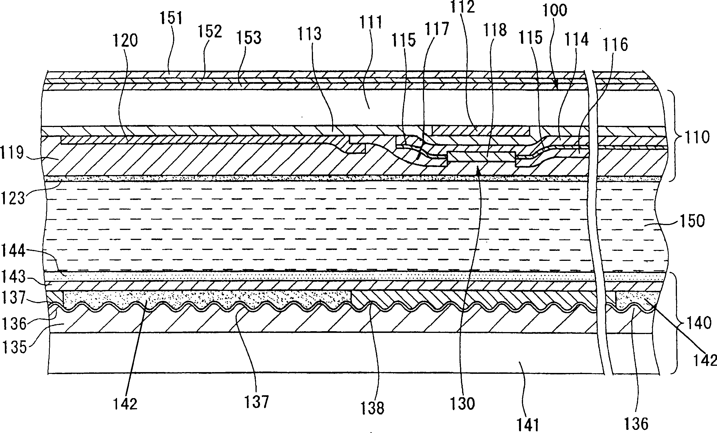
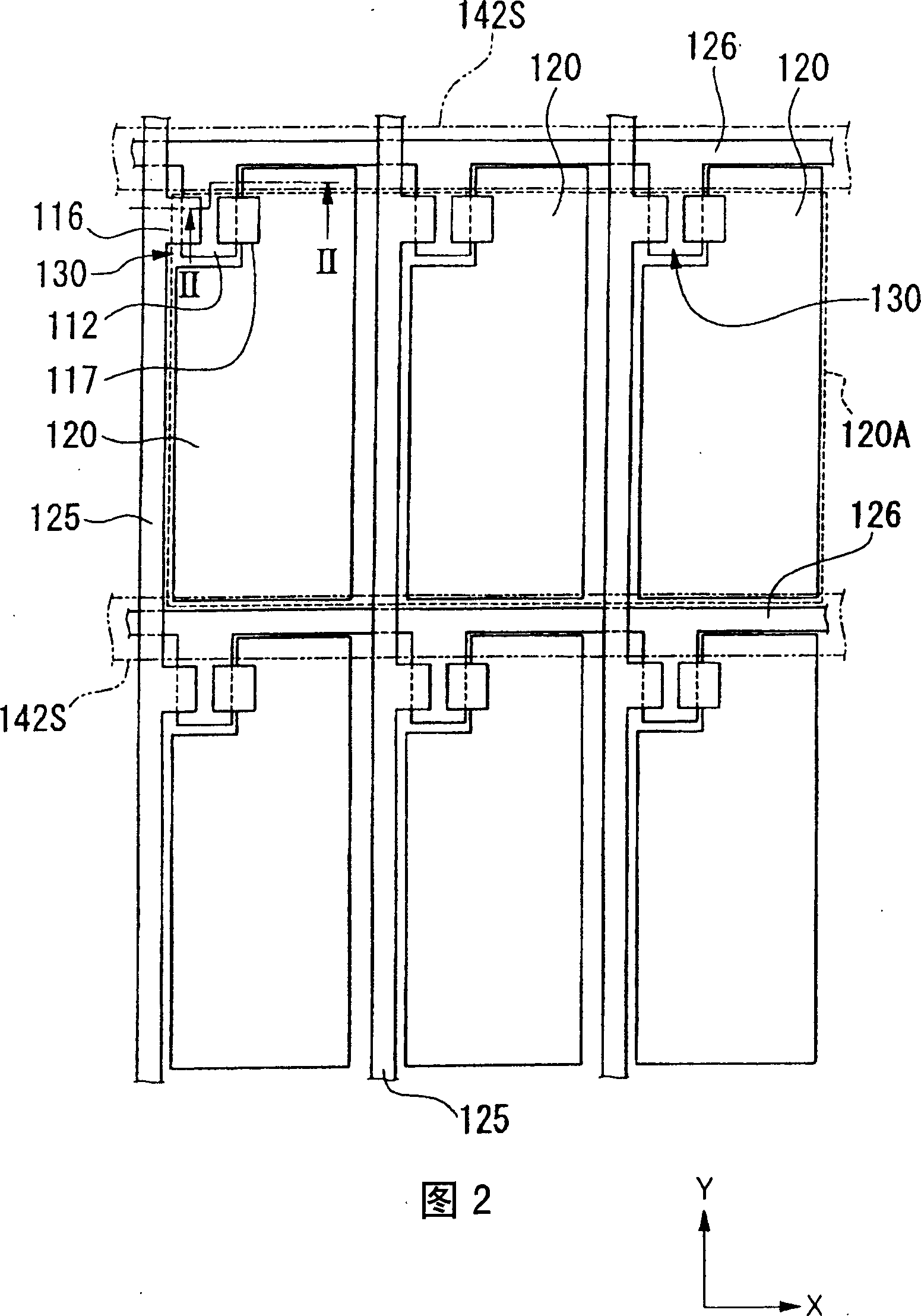
[0062] figure 1 is a cross-sectional view showing the reflective liquid crystal display device of this embodiment, and FIG. 2 shows a plan view structure of the pixel portion, as figure 1 As shown, the liquid crystal panel 100 in the reflective liquid crystal display device of this embodiment is composed of a substrate 110 on the element side, a counter substrate 140 , a liquid crystal layer 150 as a light modulation layer sandwiched between the substrates 110 and 140 , and a substrate 110. A polarizing plate 151, a first retardation film 152, and a second retardation film 153 are sequentially arranged from the ou...


PUM


Abstract

An active matrix display device includes a pair of substrates, an optical modulation layer lying between the substrates, a plurality of pixel electrodes on one of the substrates, switching elements for driving the respective pixel electrodes provided in the vicinity of the pixel electrodes, and a reflective or transflective reflecting layer formed on at least one substrate more distant from a viewer side. The reflecting layer has asymmetrical reflection properties.

Description

technical field [0001] The present invention relates to a reflective type display device that performs display using reflection of external light or an active matrix type display device that is suitable for a transflective type display device. Background technique [0002] In the field of display devices, active matrix liquid crystal display devices capable of obtaining high display quality are widely used. In such a liquid crystal display device, a liquid crystal layer is sandwiched between a pair of substrates, and a switch using a thin film transistor or a thin film diode is provided on each of a plurality of pixel electrodes arranged in a matrix on one substrate. Elements can easily obtain characteristics such as high precision through reliable switching operation of each pixel electrode. [0003] When such a liquid crystal display device adopts a reflective type or a transflective type, a diffuse reflective reflective film is formed on the lower substrate on the side f...

Claims


Application Information

Patent Timeline
Patent Type & Authority Applications(China)
IPC IPC(8): G02F1/1333G02F1/1335G02F1/1365G02F1/1368G09F9/30
CPCG02F1/133504G02F1/133553G02F1/1335
Inventor 鹿野满吉井克昌林祐三蛇口广行山口雅彦
Owner ONANOVICH GROUP
Why Eureka
Try Eureka