

Four wing non-intermeshing rotors for synchronous drive to provide improved dispersive and distributive mixing in internal batch mixers
A batch mixing and mixer technology, applied in mixers, mixers, dissolving and other directions with rotary stirring devices, can solve problems such as temperature rise
- Summary
- Abstract
- Description
- Claims
- Application Information
AI Technical Summary
Problems solved by technology
Method used
Image

Examples
Embodiment Construction
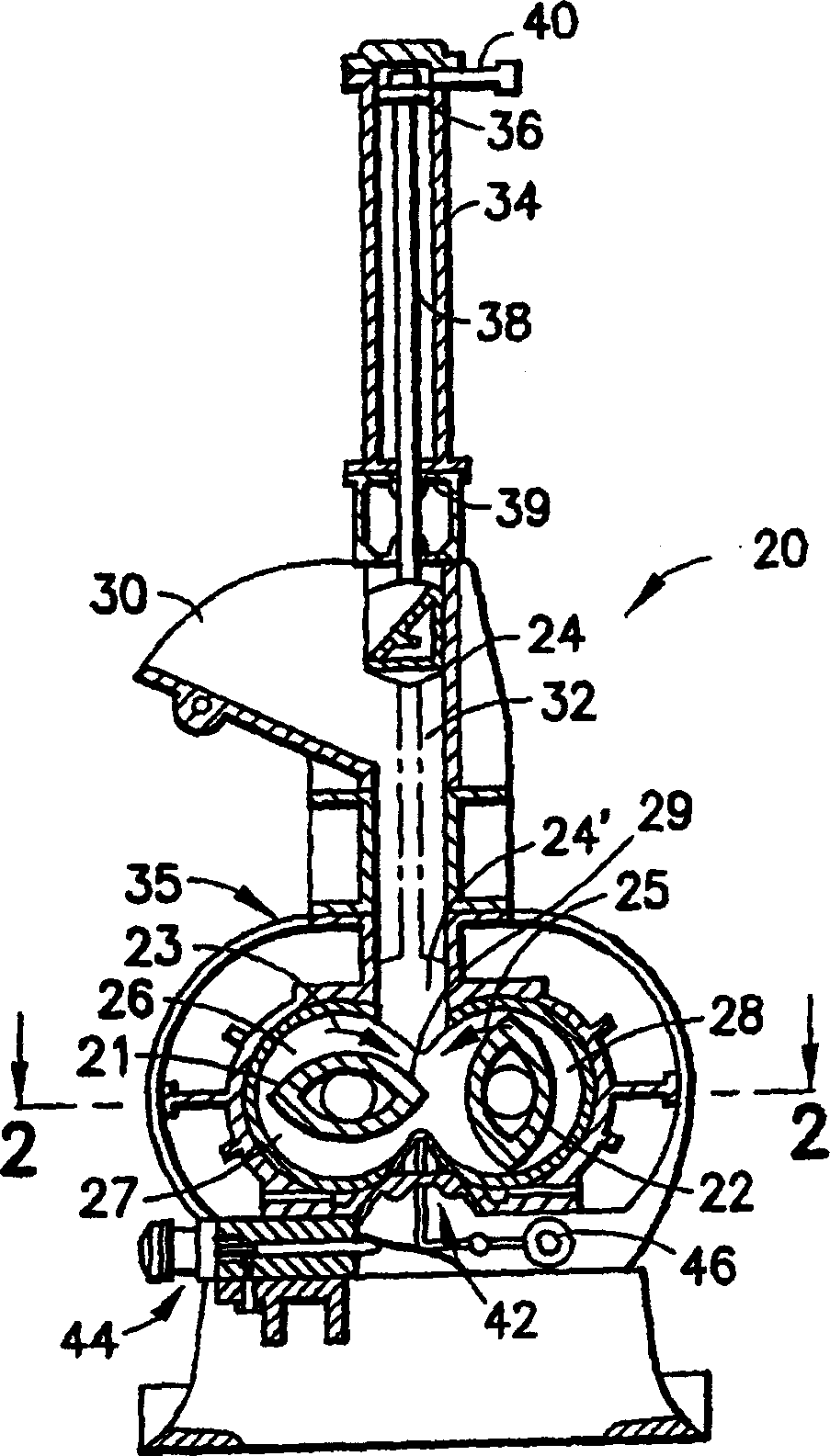
[0023] Such as figure 1 As shown, a high-intensity internal mixer of the batch type, generally designated by the reference numeral 20, in which a pair of non-intermeshing drums 21 and 22 of the present invention may be advantageously employed, comprising vertical Reciprocating pressure head 24, the pressure head in figure 1 It is movable between the raised position shown and the lowered operative position 24' shown in dotted outline. The head 24 is used to move the ingredients to be mixed down into the mixing chamber 26 . In its operating position 24', when the material is thoroughly and vigorously mixed by the fins on the two counter-rotating drums 21 and 22, as will be described below, the head possesses the ability to be mixed. The force exerted by the material in chamber 26 and the two drums rotate about spaced apart parallel horizontal axes as indicated by arrows 23 and 25. figure 1 The left drum 21 is shown rotating in a clockwise direction about its axis, and the rig...
PUM
| Property | Measurement | Unit |
|---|---|---|
| Helix angle | aaaaa | aaaaa |
| Helix angle | aaaaa | aaaaa |
| Helix angle | aaaaa | aaaaa |
Abstract
Description
Claims
Application Information