Supercharge Your Innovation With Domain-Expert AI Agents!

Image induction compensation method and its structure

A compensation method and image sensing technology, applied in electromagnetic radiation induction, optics, instruments, etc., can solve the problems of time-consuming and laborious, and achieve the effect of reducing chromatic aberration

Inactive Publication Date: 2004-03-24
UMAX DATA SYST
View PDF0 Cites 1 Cited by
  • Summary
  • Abstract
  • Description
  • Claims
  • Application Information

AI Technical Summary

Problems solved by technology

Since the optical sensor chip responds differently to the three primary lights of red light, green light, and blue light, in order to achieve the balance of sensing the three primary lights, it is necessary to adjust the color temperature of the light source. The color temperature of the lamp, and this method is very laborious
And after determining the composition of the filling, the process of making the lamp must go through two weeks, which is very time-consuming

Method used


Image

  • Image induction compensation method and its structure
  • Image induction compensation method and its structure
  • Image induction compensation method and its structure

Examples


Embodiment Construction

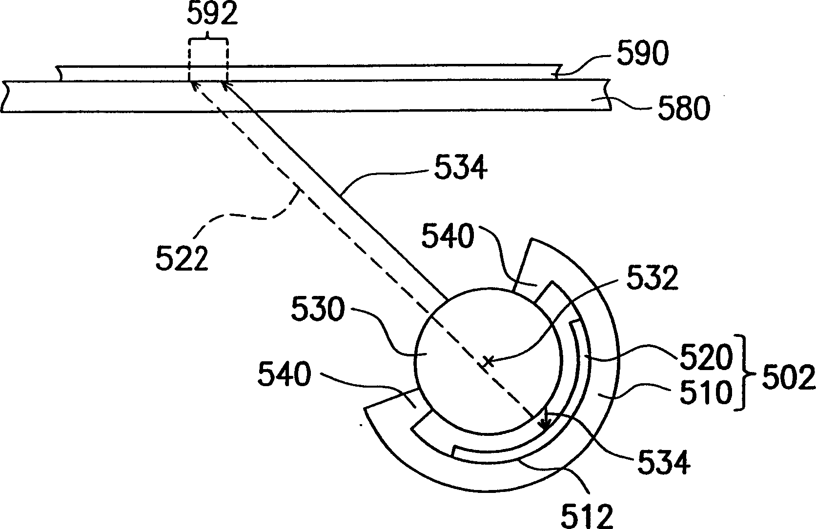
[0130] The present invention utilizes the special design of the reflective member, so that after a uniform white light irradiates the reflective member, the color of the incident white light will be changed, and the reflected light will be biased to a certain color. When the reflective member absorbs more energy for blue light and green light, its reflected light will be biased towards red; when the reflective member absorbs more energy for red light and green light, its reflected light will be biased toward blue; When red light and blue light absorb more energy, the reflected light tends to be green. In this way, the color of the reflected light can be adjusted by utilizing the difference in reflectivity of the reflective member to the three primary colors, so that the optical sensor chip can achieve a balanced response to the three primary colors of red light, green light, and blue light, thereby reducing the sensitivity of the image sensed by the scanner. chromatic aberrati...


PUM


Abstract

The invention is an image induction compensating method, including the steps: 1. providing a light source at least; 2. providing many reflecting components to reflect the light of the light source, the colors of the lights reflected by different reflecting components being different; 3. moving the reflecting components to make one among them able to reflect the light of the light source.

Description

technical field [0001] The present invention relates to an image sensing compensation method and an image sensing compensation structure, and in particular to a method for compensating the image sensing of an optical sensing chip by using a special design of a reflection member and the image sensing compensation structure. Background technique [0002] With the great improvement of computer performance and the high development of Internet and multimedia technology, in addition to using digital cameras to directly capture image patterns, other image input operations related to documents or pictures require optical scanners to capture text or The analog image of the pattern is converted into a digital signal output, which is helpful for users to display, identify, edit, store and output image files on computers or other electronic products. [0003] In the scanning system, one of the factors that determine the quality of scanning is whether the system provides an ideal color t...

Claims


Application Information

Patent Timeline
Patent Type & Authority Applications(China)
IPC IPC(8): G02B5/08G02B26/10G06K7/10
Inventor 陈俊仁杨尚谕萧俊义庞则辉
Owner UMAX DATA SYST
Features
  • R&D
  • Intellectual Property
  • Life Sciences
  • Materials
  • Tech Scout
  • Unparalleled Data Quality
  • Higher Quality Content
  • 60% Fewer Hallucinations
Learn More