Antenna unit and communication device including same

An antenna unit and antenna technology, applied to antennas, resonant antennas, and devices that enable antennas to work in different bands at the same time, can solve the problems of reduced efficiency of fed radiating electrodes 22 and non-fed radiating electrodes, and reduction of antenna 20 characteristics, etc. , to achieve the effect of improving the antenna efficiency

Inactive Publication Date: 2004-03-31
MURATA MFG CO LTD
View PDF0 Cites 16 Cited by
  • Summary
  • Abstract
  • Description
  • Claims
  • Application Information

AI Technical Summary

Problems solved by technology

However, when the dielectric substrate 21 is made small and low in section, the efficiency of the fed radiation e

Method used


Image

  • Antenna unit and communication device including same
  • Antenna unit and communication device including same
  • Antenna unit and communication device including same

Examples


Embodiment Construction

[0032] Preferred embodiments of the present invention will now be described with reference to the accompanying drawings.

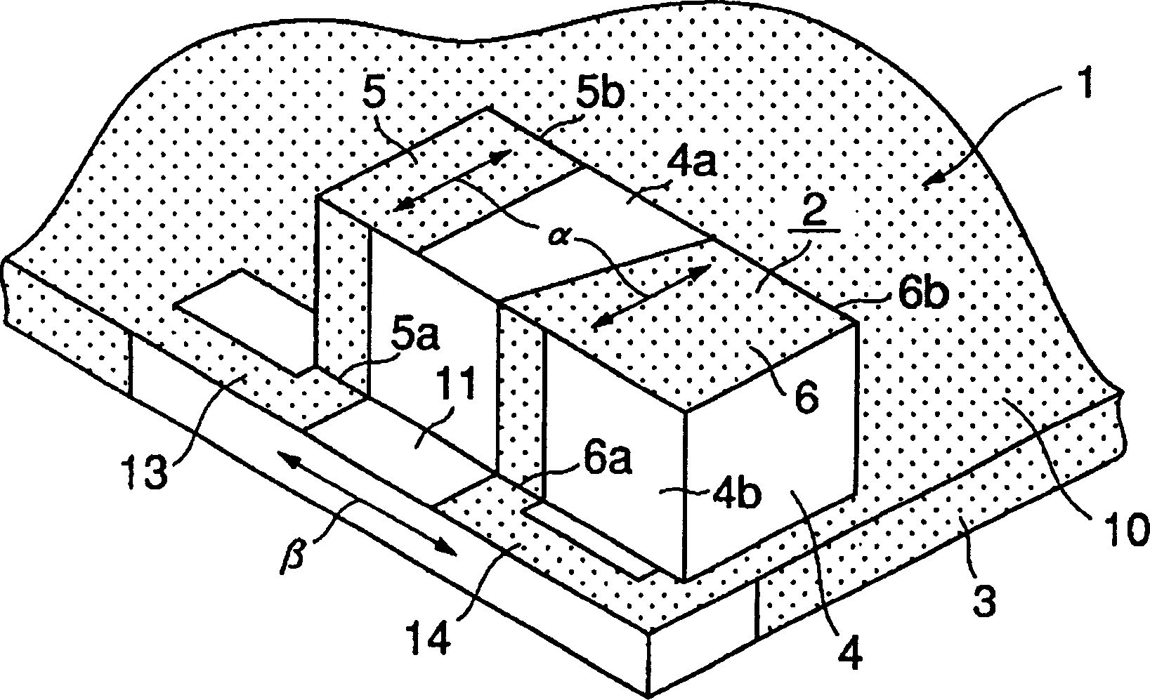
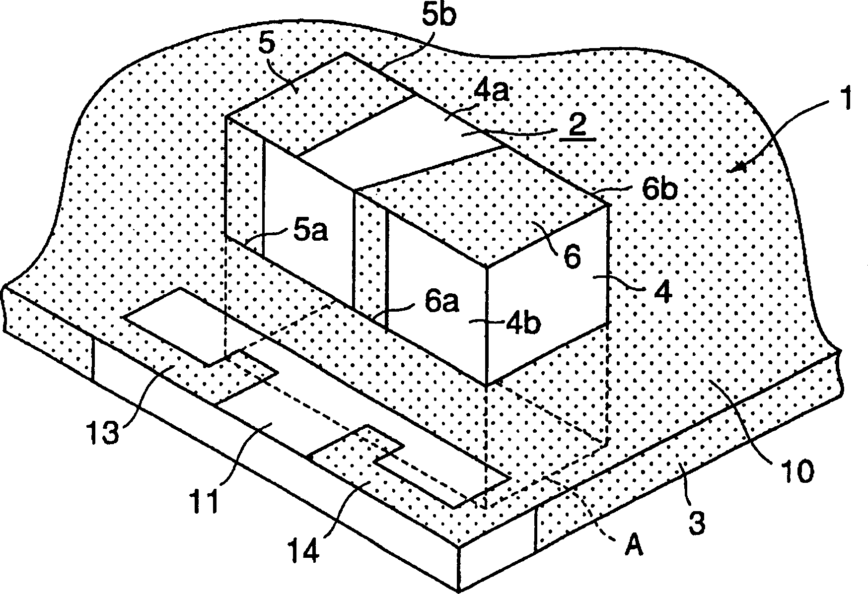
[0033] Figure 1A is a perspective view of the antenna unit 1 according to the first preferred embodiment of the present invention. Figure 1B is a schematic component diagram of the antenna unit 1 . figure 2 Shows Figure 1A and 1B The rear of the antenna unit 1 is shown.

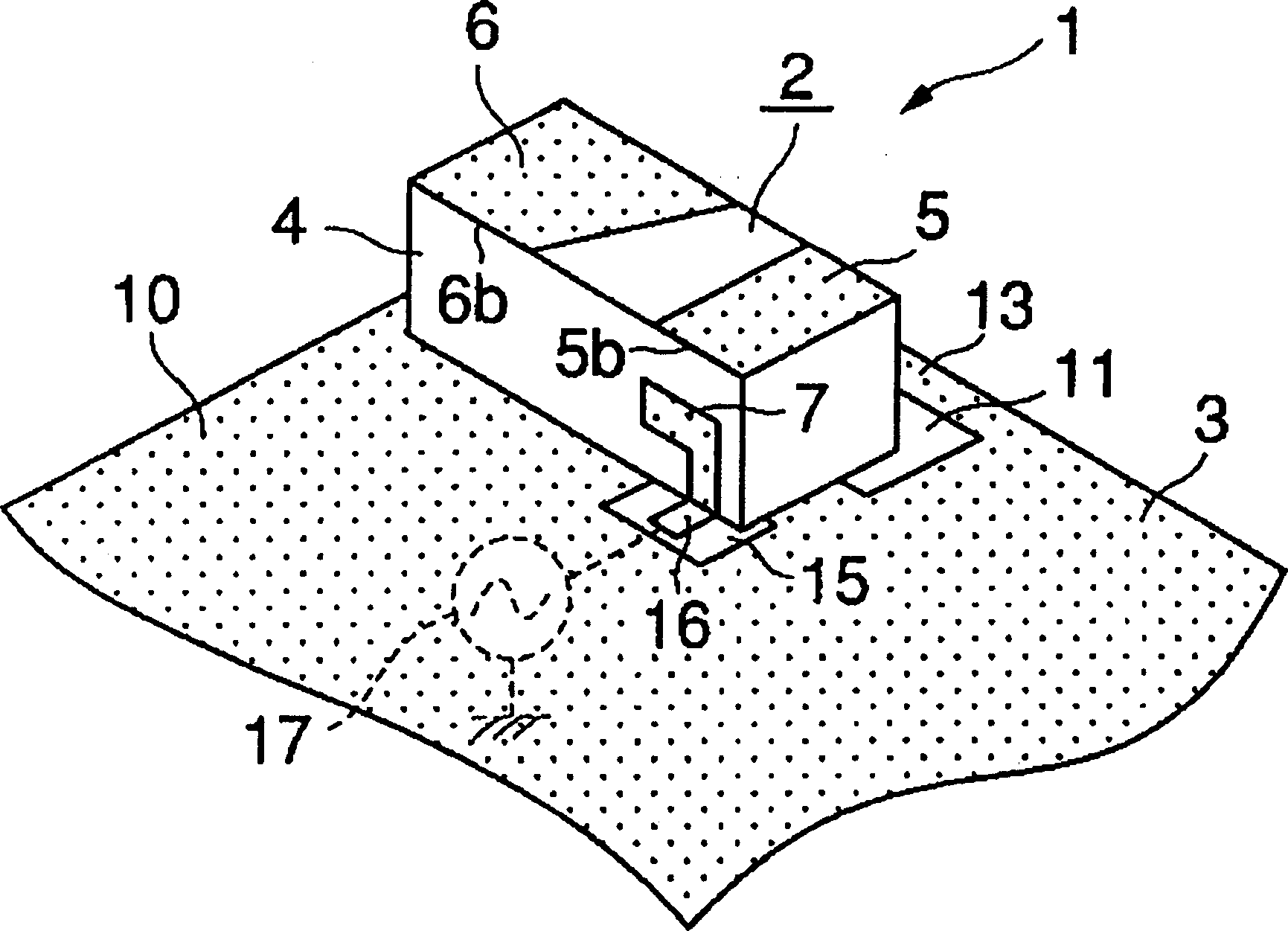
[0034] The antenna unit 1 includes a chip-shaped antenna body 2 and a circuit substrate 3 for mounting the antenna body 2 thereon. image 3 It is an expanded view of the antenna body 2 .

[0035] The antenna body 2 includes a dielectric substrate 4 and a feeding radiating electrode 5 , a non-feeding radiating electrode 6 , a feeding electrode 7 and a ground electrode 8 disposed on the dielectric substrate 4 . Specifically, the feeding radiation electrode 5 and the non-feeding radiation electrode 6 are arranged so as to be adjacent to each other at a predetermined distance on the u...


PUM


Abstract

An antenna unit includes an antenna body having a fed radiation electrode and a non-fed radiation electrode that generate a double resonance state and that are mounted on a dielectric substrate, and a substrate for mounting the antenna body thereon. A ground electrode is disposed on the substrate in a predetermined area other than a ground-electrodeless portion provided on the substrate. The ground-electrodeless portion extends from at least one portion of an antenna-body mounting area so as to extend off of and away from the antenna-body mounting area. Grounding ends of the fed radiation electrode and the non-fed radiation electrode are connected to the ground electrode via grounding lines disposed on a predetermined portion of the ground-electrodeless portion, the predetermined portion being outside the antenna-body mounting area.

Description

(1) Technical field [0001] The present invention relates to an antenna unit that can be used in a communication terminal or other suitable device, and also to a communication device comprising such an antenna unit. (2) Background technology [0002] Figure 12 is a diagrammatic perspective view of the antenna 20 provided within the communication device. This antenna 20 has a dielectric substrate 21, a feeding radiating electrode 22 and a non-feeding radiating electrode 23 mounted on the dielectric substrate 21, and is located on a predetermined side surface of the dielectric substrate 21 and feeds a signal to the feeding radiating electrode 22. A feed electrode (not shown) of the dielectric substrate 21, and an antenna ground terminal (not shown) disposed on the entire lower surface of the dielectric substrate 21. [0003] The feeding radiation electrode 22 has both ends. One of the two ends is the ground terminal 22a, and the other end is the feeding terminal to which the ...

Claims


Application Information

Patent Timeline
IPC IPC(8): H01Q13/08H01Q1/24H01Q1/38H01Q5/00H01Q9/04
CPCH01Q9/0457H01Q5/0062H01Q1/38H01Q5/378H01Q13/08
Inventor 石原尚南云正二川端一也
Owner MURATA MFG CO LTD
Why Eureka
Try Eureka