Machining process of spline inside blind hole in shaft end
A processing method and internal spline technology are applied in the field of metal precision cutting to achieve the effects of improving processing efficiency, realizing interchangeability and improving rigidity
Inactive Publication Date: 2004-04-07
JIANGSU GANGYANG STEERING SYST
View PDF0 Cites 12 Cited by
- Summary
- Abstract
- Description
- Claims
- Application Information
AI Technical Summary
Problems solved by technology
[0003] The object of the present invention is to overcome the disadvantages of the existing method of slotting and machining the internal splines of blind holes at shaft ends, and provide a method for processing internal splines in blind holes at shaft ends with simple operation, high production efficiency and improved machining accuracy.
Method used
View moreImage
Smart ImageViewing Examples

Examples
Embodiment Construction
[0010]
Login to View More PUM
 Abstract
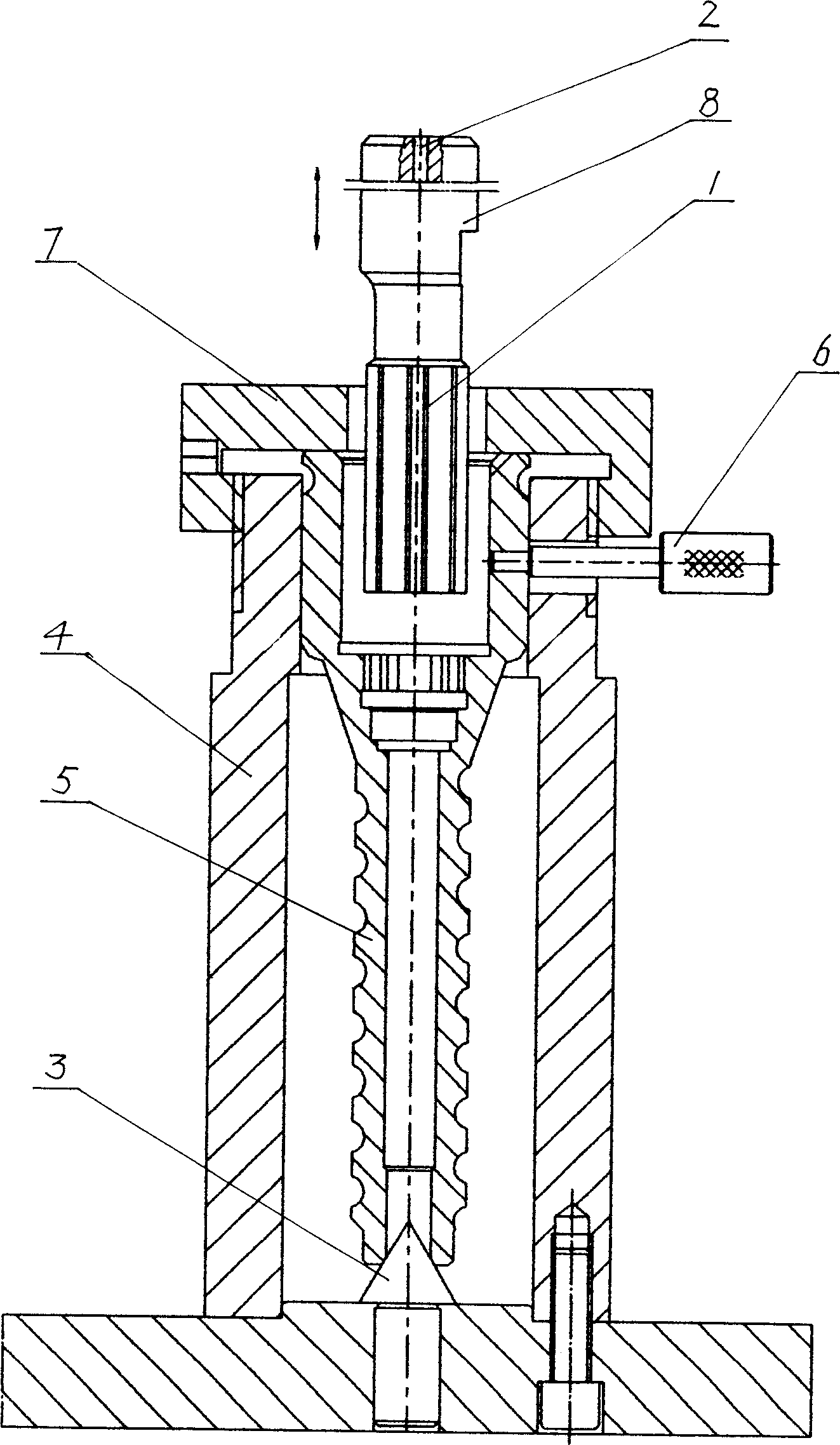
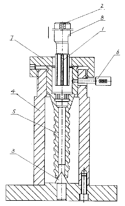
The present invention is machining process of spline inside blind hole in shaft end in high maching speed and high precision. The machining process includes setting the machining shaft vertically inside positioned fixture for positioning and clamping with the end to be machined being in the top; and driving the toothed forming pushing broach for cutting via vertical reciprocation after the working head of the press is positioned. The pushing broached amount is designated to the forming pushing broaches, and, for example, the pushing broached amount for rectangular tooth is designated to 8-11 forming pushing broaches. During the cutting, the toothed forming pushing broaches are used successively in the order from small outer diameter one to large outer diameter one.
Description
technical field [0001] The invention relates to a method for processing a spline in a blind hole at a shaft end, and belongs to the technical field of metal precision cutting. Background technique [0002] The shaft is an indispensable part of the machine, and sometimes the shaft needs to be designed with splines due to its structure. The conventional production method of external splines is that milling is the main method for single piece or small batch, and broaching is the main method for mass production. The processing of internal splines is not as easy as that of external splines, especially the processing accuracy of internal splines in blind holes at shaft ends is greater. The conventional method of cutting internal splines in blind holes at shaft ends is single-tooth slotting processing, and the shaft to be processed is positioned It is clamped on the slotting machine table, divided into equal parts according to the number of teeth with a circular indexer, and singl...
Claims
Login to View More Application Information
Patent Timeline
 IPC IPC(8): B23D13/00B23P17/02
Inventor 宋海兵张如清王春宏
Owner JIANGSU GANGYANG STEERING SYST