Double-wire powering trolleybus pantograph

A trolleybus and pantograph technology, applied in the direction of collectors, electric vehicles, power collectors, etc., can solve problems such as difficulty in automatically rising to the line and connecting to the network.

Inactive Publication Date: 2004-04-07
SHANGHAI JIAO TONG UNIV
View PDF1 Cites 38 Cited by
  • Summary
  • Abstract
  • Description
  • Claims
  • Application Information

AI Technical Summary

Problems solved by technology

[0005] The present invention has substantive features and significant progress. The bow-top conductive slide plate of the present invention is longer than the bow-top conductive slide plate of the pantograph used in electric locomotives and urban rail vehicles, and the bow-top conductive slide plate is partially isolated and insulated in the middle to become a double receiving Therefore, it can contact double wires, and the double lines can receive current at the same time; change the trolley bus collector pole and groove-shaped collector slide shoes into pantograph and pantograph forms, and adopt a longer bow-top conductive slide structure , in conjunction with the use of the trolleybus station charging special catenary that widens the line spacing of the double contact wires, so that the current receiving part of the bow top of the pantograph will automatically lift and align with the trolleybus ...

Method used


Image

  • Double-wire powering trolleybus pantograph
  • Double-wire powering trolleybus pantograph
  • Double-wire powering trolleybus pantograph

Examples


Embodiment Construction

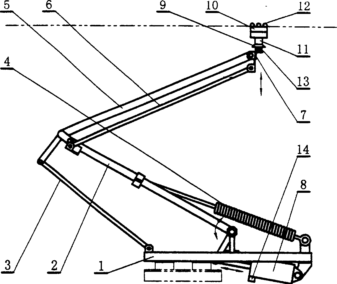
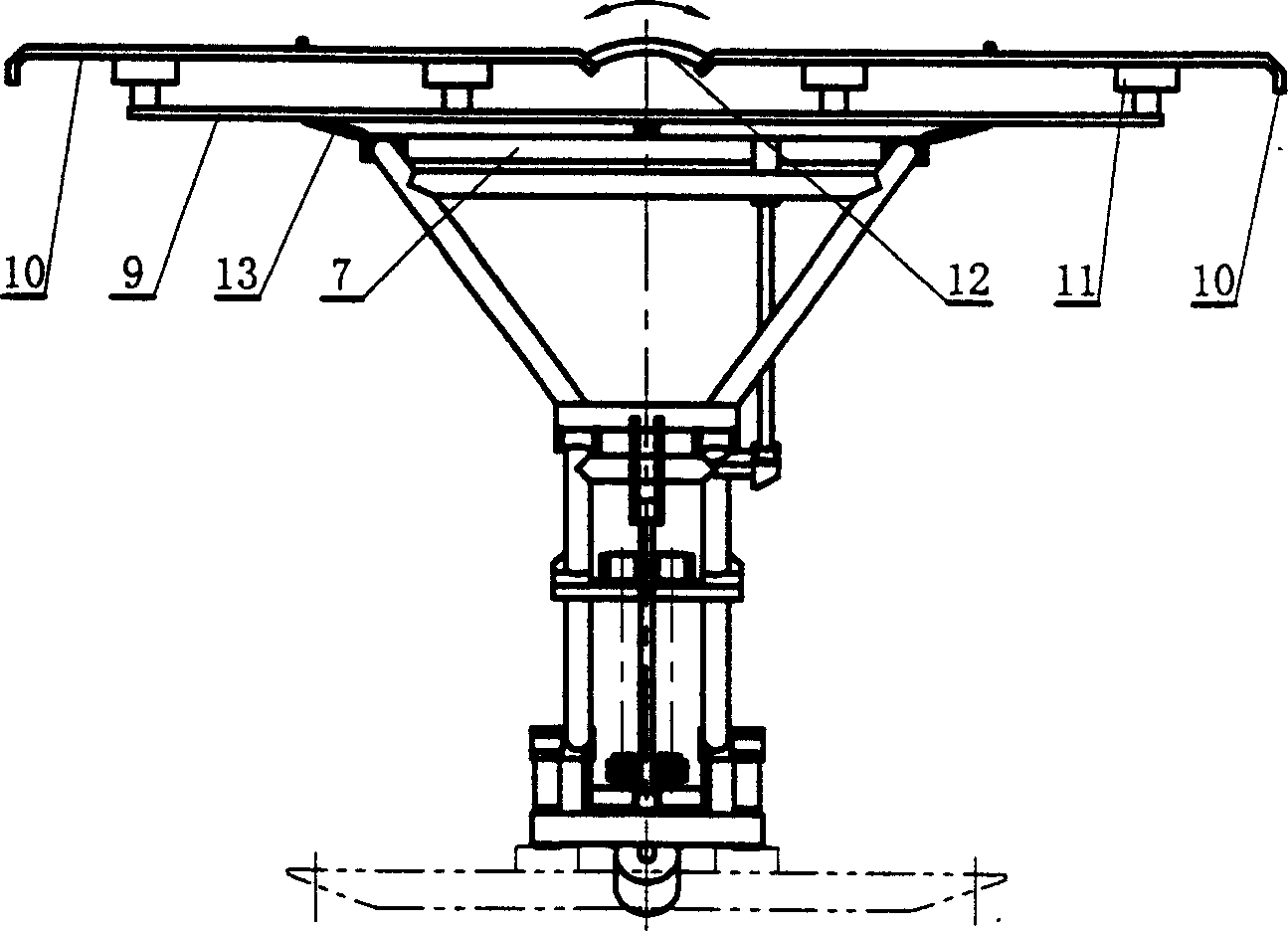
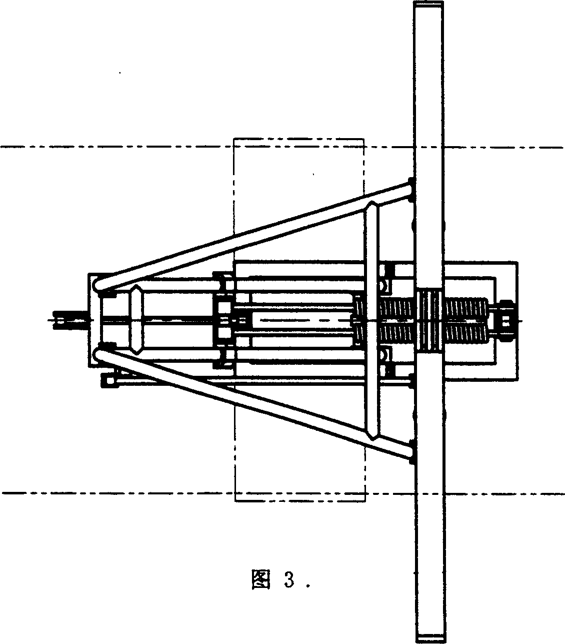
[0011] Such as figure 1 , Figure 2 and As shown in Fig. 3, the present invention includes: underframe 1, lower arm bar 2, pull bar 3, bow spring 4, upper arm bar 5, balance bar 6, bow head seat bar 7, cylinder 8, bow top bar 9, Bow top conductive slide plate 10, insulating seat 11, insulating rod 12, bow head spring 13, travel switch 14, the lower end of lower arm bar 2 and pull bar 3 are all movably connected with underframe 1, and the upper ends of lower arm bar 2 and pull bar 3 are all movably connected. It is movably connected with the lower end of the upper arm 5, the lower end of the balance bar 6 is movably connected with the upper end of the lower arm 2, and the upper ends of the upper arm 5 and the balance bar 6 are both movably connected with the cross bar 7 of the bow seat, and the bow top conductive slide plate 10 is in the The middle part is divided into two halves by several insulating rods 12, and the two halves of the bow top conductive slide plate 10 are res...


PUM


Abstract

The double-wire powering trolleybus bow collector used in city public traffic includes bottom frame, lower arm rod, pull rod, bow raising spring, upper arm rod, balance rod, head seat cross rod, cylinder, top cross rod, electrically conducting top sliding board, insulating seat, insulating rod and top spring. The six parts including bottom frame, lower arm rod, pull rod, upper arm rod, balance rod and head seat cross rod constitute two duplex planar quadric crank mechanisms with rods connected flexibly. The electrically conducting top sliding board is separated by the middle insulating rod into two current collectors fixed via the insulating seat on the top cross rod; and the top cross rod is connected flexibly to the head seat cross rod, with two ends being connected via the top spring. When the low arm rod is oscillated by the cylinder on the bottom frame and the bow raising spring, the electrically conducting top sliding board will ascend or descent. The present invention has good contact performance, etc.

Description

technical field [0001] The invention relates to a pantograph for a trolleybus, in particular to a pantograph for a double-wire receiving type trolleybus, which belongs to the field of urban public transportation. Background technique [0002] At present, the trolley bus used for urban public transportation has the characteristics of low noise, no emission pollution, quick start and fast uphill, but due to the existence of overhead power supply contact wire network, roof collector pole and collector slipper, it makes the The electric car cannot overtake the electric car, and if there is an accident where the collector slipper jumps off the wire during driving, it will easily lead to traffic jams and affect the landscape above the city streets; it uses large-capacity batteries or capacitors to store energy and stop for fast charging. Most of the overhead power supply catenary network can be canceled, and only a section of special charging catenary is reserved in the station ar...

Claims


Application Information

Patent Timeline
IPC IPC(8): B60L5/20
Inventor 程晓鸣陈杰林忠钦殷跃红李忠学
Owner SHANGHAI JIAO TONG UNIV
Why Eureka
Try Eureka