Method for manufacturing wound stator core of generator for automobile and winding machine and reshaping machine
A technology for automobile generators and stator iron cores, which is applied in the manufacture of stator/rotor bodies, etc., can solve the problems of easy occurrence of gaps, affecting the performance of generators, low material utilization rate, etc., and achieves low replacement costs, equipment processing and installation time. The effect of short, improved material utilization
- Summary
- Abstract
- Description
- Claims
- Application Information
AI Technical Summary
Problems solved by technology
Method used
Image
Examples
Embodiment 1
[0031] Such as Figure 1 ~ Figure 4 As shown, the manufacturing method of the winding type automobile generator stator core is:
[0032] 1. Uncoiling and leveling, put the 1.0 mm thick disc-shaped steel strip on the uncoiler, adjust the leveling speed of the leveling machine according to the speed of the punching machine and the step distance of the die and make it match, and the uncoiling is driven by the leveling machine The machine is running, and the steel belt is opened sequentially from the outer circle;
[0033] 2. Stamping, using a press for stamping, the steel strip is stamped in three steps through a progressive stamping die, and then divided into two continuous toothed strips that are not connected to each other and have the same size. The first step is to stamp the steel The R arc with the end, the second step of stamping the U-shaped end hole, and the third step of stamping the side hole. The stamping die is a cemented carbide mosaic structure. The pressure of th...
Embodiment 2
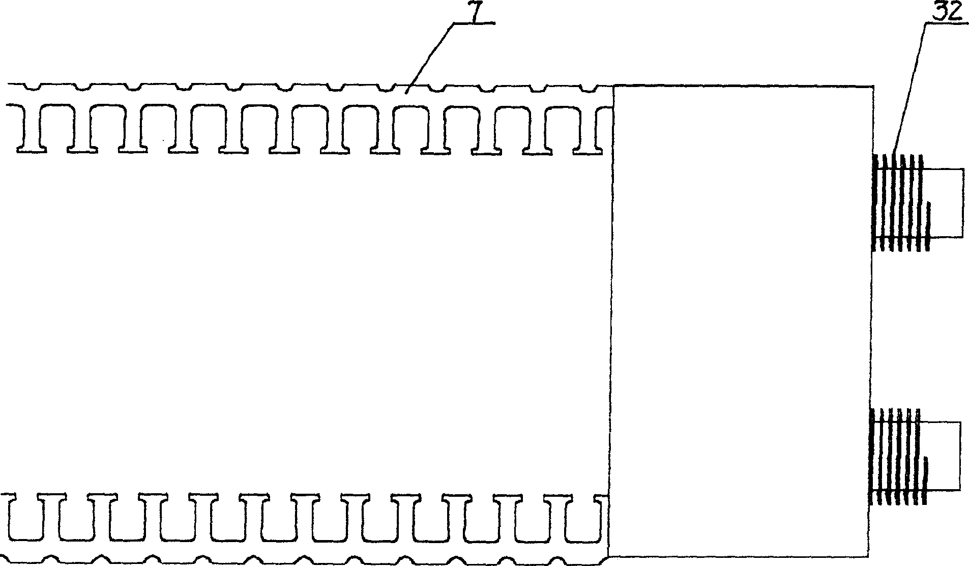
[0039] Such as Figure 5 ~ Figure 12As shown, the winding machine used in the production method of the above-mentioned winding type automobile generator stator core includes a frame 18, a brake motor 1 and a reducer 2 are installed at the bottom of the frame 18, and a transmission box is arranged on the top of the frame 18 12. The transmission case 12 is connected with the speed reducer 2 through a pulley 17 and a belt 16, and the speed reduction device 2 and the transmission case 12 constitute a reduction transmission device. On the output shaft of transmission case 12, be connected with outer edge and be provided with the drive pulley 4 of several evenly distributed convex circles, the convex circle on the said drive pulley 4 matches with strip material 7 side R arc shapes. On the transmission box 12, corresponding to the position on both sides of the driving wheel 4, the centering wheel 10 is respectively installed by screws and nuts, and the position of the axis of the cen...
Embodiment 3
[0042] Figure 13~ Figure 17 As shown, the used shaping device for the production method of the above-mentioned winding type automobile generator stator core includes a lower backing plate 21, a lower template 22 is connected to the lower backing plate 1 by screws or a pressing plate, and a lower template 22 is provided on the upper surface of the lower template 22. The template 22 is an integrated guide post 36, on which the upper template 20 is placed, and the position of the corresponding guide post 36 on the bottom surface of the said upper template 20 is provided with a guide sleeve 31, and the upper template 20 is mounted on the middle part of the bottom surface of the upper template 20 by screws. Die fixed plate 29, the inner surface bottom of patrix fixed plate 29 is provided with shoulder 30, annular patrix 28 and upper backing plate 38 are housed in patrix fixed plate 29, and lower mold base 25 is installed by screw on lower template 22 , the inner surface of the low...
PUM
 Abstract
Description
Claims
Application Information
 - R&D
- Intellectual Property
- Life Sciences
- Materials
- Tech Scout
- Unparalleled Data Quality
- Higher Quality Content
- 60% Fewer Hallucinations
Browse by: Latest US Patents, China's latest patents, Technical Efficacy Thesaurus, Application Domain, Technology Topic, Popular Technical Reports.
© 2025 PatSnap. All rights reserved.Legal|Privacy policy|Modern Slavery Act Transparency Statement|Sitemap|About US| Contact US: help@patsnap.com


