Supporting structure for vehicle power source

A technology of vehicle power and support structure, applied in power plant, vehicle parts, jet propulsion and other directions, can solve the problems of power source roll/tilt, short distance, easy to feel by passengers, etc.

Inactive Publication Date: 2004-04-21
HONDA MOTOR CO LTD
View PDF1 Cites 14 Cited by
  • Summary
  • Abstract
  • Description
  • Claims
  • Application Information

AI Technical Summary

Problems solved by technology

[0009] However, in a center-of-gravity mount type support structure, the engine and transmission are arranged and held on a mount that is disposed on a frame member such as a sub-member, so that the center of elasticity formed by the entire mount is easily lower than the engine. and the center of gravity of the transmission
Therefore, the power source can easily roll and / or tilt with the vehicle's motion
[0010] Also, there is such a problem that passengers can easily feel the roll / tilt of the power source, and there is no feeling that the power source and the vehicle body are integrated, and therefore, a good feeling of driving safety / driving performance cannot be obtained
[0011] On the other hand, in figure 1 In the shown general inertial main shaft type support structure, the mount member 101 is arranged on the side frame or its side, so it is difficult to adopt a double vibration isolation structure, so that, unlike the center-of-gravity mount type, the mount member arrangement and Retained on the side frame elastically supported by the body frame for mounting frame part 101
Moreover, there is such a problem that the distance from the side engine mount 112a and transmission mount 112b on both sides to the cab is very short, so the sound and vibration that cannot be completely blocked by the mount part 101 will easily pass to passengers

Method used


Image

  • Supporting structure for vehicle power source
  • Supporting structure for vehicle power source
  • Supporting structure for vehicle power source

Examples


Embodiment Construction

[0035] A preferred embodiment of the present invention will be described in detail below with reference to the accompanying drawings.

[0036] a. Support structure of vehicle power source

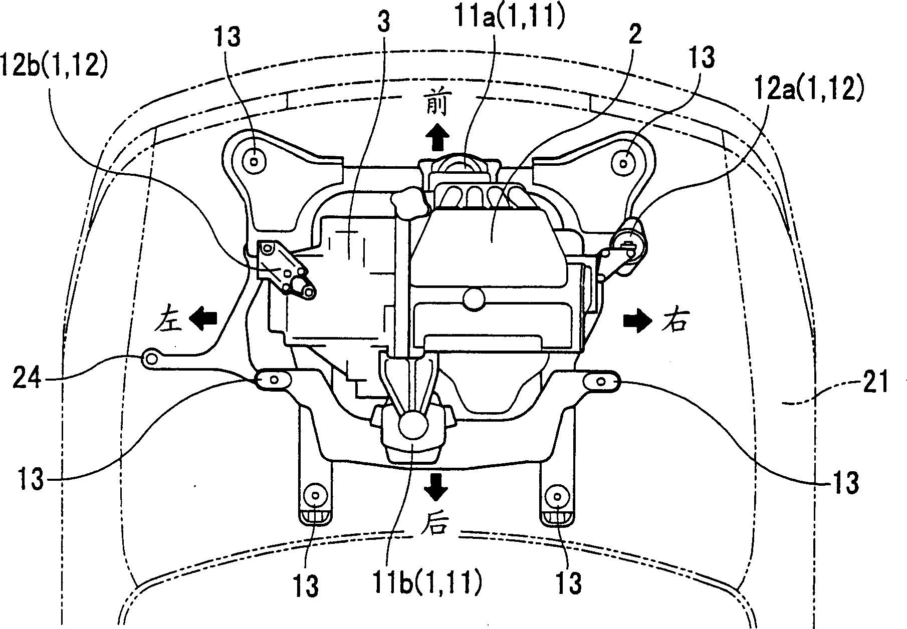
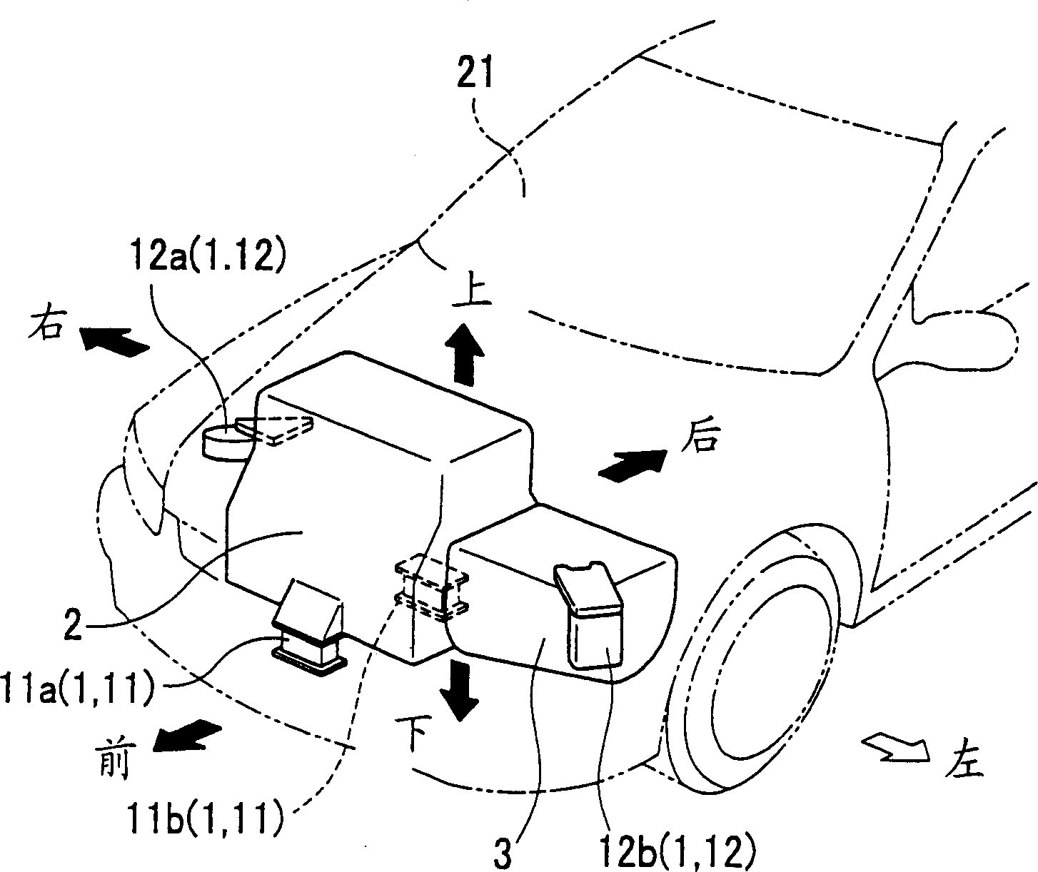
[0037] Figure 2A and 2B A plan view and a perspective view respectively show the overall structure of a support structure of an embodiment of the present invention. Figure 3A , 3B 3C and 3C show a plan view, a rear view and a side view, respectively, of a schematic structure of a support structure according to an embodiment of the present invention.

[0038] In the embodiment, the support structure is designed to support the engine 2 as the power source of the vehicle on the vehicle body 21 through a plurality of elastic mounting frame components 1 .

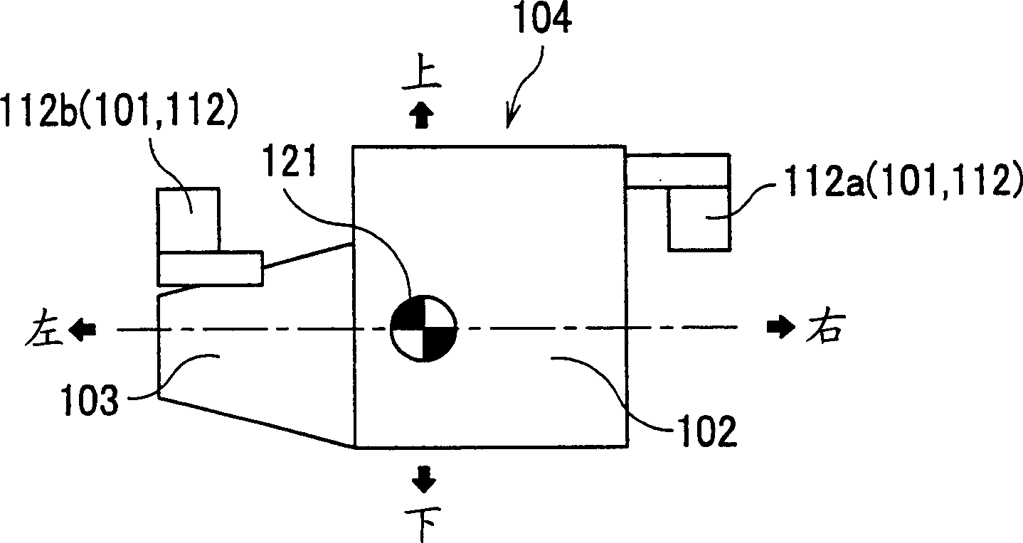
[0039] Here, the engine 2 is designed such that the transmission 3 is connected to one end of its crankshaft (not shown in the figure), and the crankshaft is arranged laterally relative to the vehicle body 21 .

[0040] Such a pluralit...


PUM


Abstract

A supporting structure of a vehicle power source consists of a plurality of mount members with elasticity through which a power source is mounted on a vehicle body; first mount members for primarily sharing the weight of the power source and at least one of the first mount members, which is supported by the vehicle body at a first height lower than the height of gravity center of the power source, is attached to a sub-frame; and second mount members for secondarily sharing the weight of the power source and the second mount members, which have a spring effect in at least one of longitudinal and lateral directions of the vehicle body, are attached to the vehicle body at a second height higher than the gravity center of the power source. In the supporting structure, the height of elasticity center of the structure defined by the first and second mount members is set to be higher than the gravity center of the power source.

Description

technical field [0001] The invention relates to a supporting structure of a vehicle power source, which is used for the vehicle body to support the vehicle power source through a plurality of elastic mounting frame parts. Background technique [0002] Generally, for such a support structure of a vehicle power source, there are a so-called center-of-gravity mount type support structure and an inertial spindle type support structure. [0003] In the center-of-gravity mount type, the elastic center of the mount corresponds substantially to the center of gravity, on which the engine and transmission are arranged intuitively on the support structure and on the mounts of the frame parts, such as the sub-frame. [0004] When the engine is arranged longitudinally, in many cases, the center of elasticity of the entire mount is set higher than the center of gravity of the engine by inclining the left and right side mounts arranged near the center of gravity. [0005] As for the inert...

Claims


Application Information

Patent Timeline
Patent Type & Authority Applications(China)
IPC IPC(8): B60K5/12
CPCB60K5/1208B60K5/1216
Inventor 吉田裕之宫川一夫纸英树渡边贤
Owner HONDA MOTOR CO LTD
Why Eureka
Try Eureka