Pressure generator

A technology for generating devices and pressure, which is applied in the field of pressure generating devices, and can solve the problems that parts cannot be lifted gently and the conveying device becomes larger

Inactive Publication Date: 2004-04-21
KOGANEI +1
View PDF0 Cites 4 Cited by
  • Summary
  • Abstract
  • Description
  • Claims
  • Application Information

AI Technical Summary

Problems solved by technology

In addition, when a jet pump is used to generate vacuum, it is usually necessary to supply compressed air from the nozzle to the diffuser, so it is necessary to install an air pressure generating source such as a compressor on the parts conveying device, and the conveying device becomes larger.
[0005] For example, in order to adjust the posture of the parts transported by the bulk feeder to the specified output port while positioning, in the case of vacuum suction parts, for the usual parts by vacuum suction, when the parts are supplied from the bulk feeder The part cannot be lifted gently when the part is lifted by the delivery head to install its plate

Method used


Image

  • Pressure generator
  • Pressure generator
  • Pressure generator

Examples


Embodiment Construction

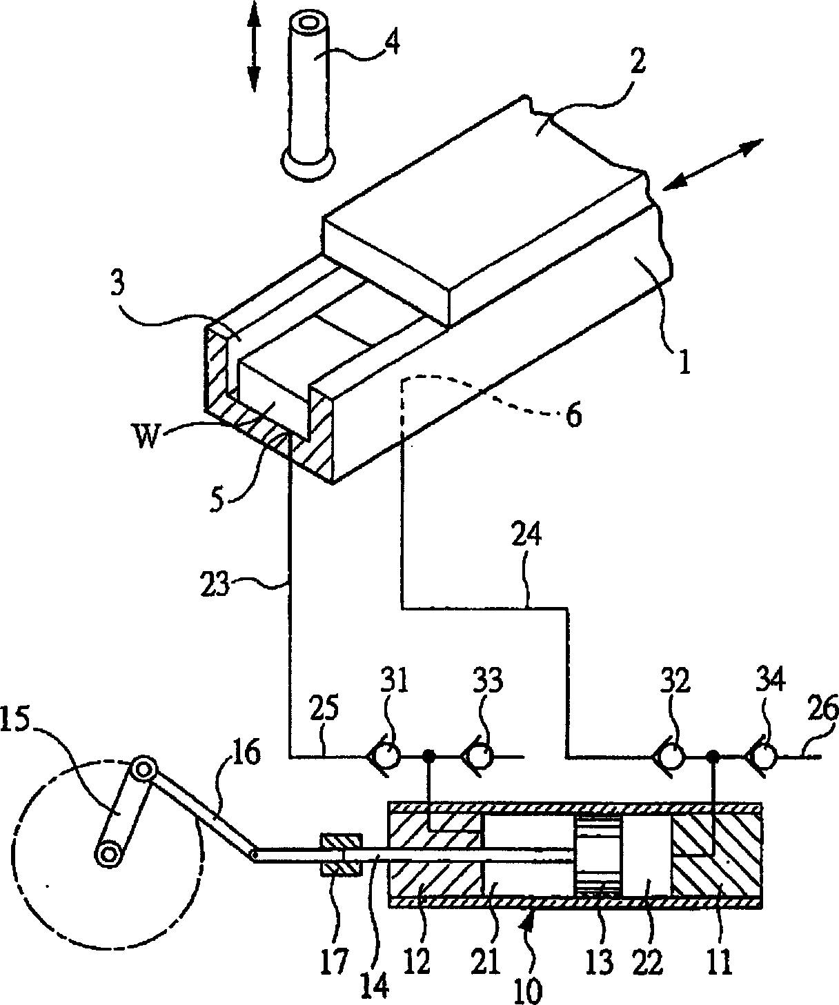
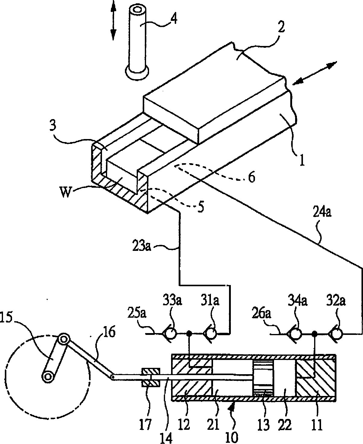
[0031] figure 1 The pressure generating device shown is suitable for a parts transfer device that transfers and supplies parts such as semiconductor chips from a parts supply part formed by a bulk feeder to a mounting substrate not shown in the figure, and positions the parts by supplying negative pressure air to the parts transfer device In the specified position, in order to take out the leading part to the outside. The pressure generating device is used to generate negative pressure.

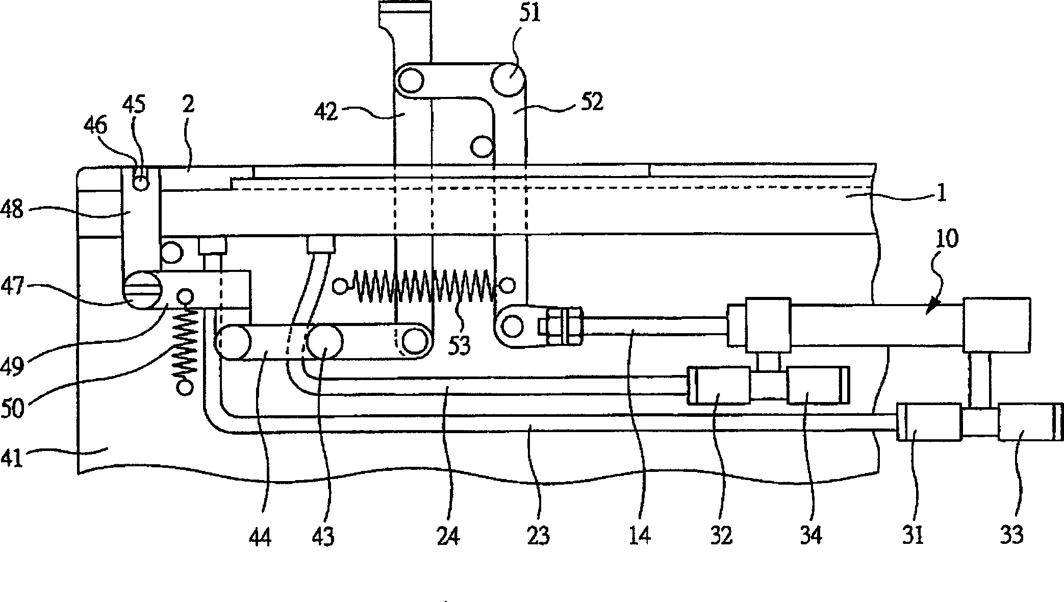
[0032] exist figure 1 The part output port of the bulk feeder is shown in , and the parts W are arranged neatly along the guide rail 1 and transported. On the guide rail 1, an openable shutter 2 freely reciprocating in a linear direction as shown by an arrow is provided, and the component outlet 3 is opened and closed by the shutter 2. As shown in FIG. In the state where the component output port 3 is opened by the shutter 2, after the suction tool 4 installed on the delivery head (not sho...


PUM


Abstract

A pressure generator, wherein a piston 13 is stored in a cylinder 10 reciprocatingly in axial direction, a piston rod 14 fixed to the piston 13 is projected to the outside through a rod cover 12, check valves 31, 32 for negative pressure allowing air to flow into expansion and contraction chambers 21, 22 and stopping air to flow in reverse direction are installed in negative pressure feed passages 23, 24 connected between the expansion and contraction chambers 21, 22 and operating ports 5, 6, check valves 33, 34 for exhaust gas allowing air to flow from the expansion and contraction chambers 21, 22 to the outside and stopping air to flow in reverse direction are installed in exhaust gas flow passages 25, 26 for communicating the expansion and contraction chambers 21, 22 with the outside, and the negative pressure feed passages 23, 24 are brought into a vacuum state by the reciprocating motion of the piston 13.

Description

technical field [0001] The present invention relates to a pressure generating device for generating pulsed negative or positive pressure air, for example, to a device for generating the posture and positioning of parts in a transfer unit for transferring small and light parts such as semiconductor chips, capacitors, and resistors. A pressure generating device for positive or negative air pressure. Background technique [0002] When mounting small and light components such as semiconductor chips, capacitors, and resistors on a mounting board or a breadboard, they are transported from the component supply unit to the mounting board or breadboard by a chip holder. When mounting relatively small parts, the parts are placed in a state of being housed in the tape feeder or the bulk feeder and placed on the parts supply unit. Tape feeders place parts on a tape at regular intervals, and draw out parts while feeding the tape. On the other hand, the bulk feeder arranges the parts li...

Claims


Application Information

Patent Timeline
Patent Type & Authority Applications(China)
IPC IPC(8): F04B5/02F04B39/10
CPCF04B39/10F04B39/1013F04B5/02F04B27/02
Inventor 宫下幸宏篠崎诚齐藤浩二神村淳男
Owner KOGANEI
Why Eureka
Try Eureka