Safety braker of lift

A technology for safe braking and elevators, which is applied in the direction of transportation and packaging, elevators, etc., and can solve problems such as falling and sliding

Inactive Publication Date: 2004-04-28
INVENTIO AG
View PDF3 Cites 18 Cited by
  • Summary
  • Abstract
  • Description
  • Claims
  • Application Information

AI Technical Summary

Problems solved by technology

The biggest disadvantage of the usual safety brakes is that the elevator car stops at a floor level and will slip or fall uncontrollably when loaded

Method used


Image

  • Safety braker of lift
  • Safety braker of lift
  • Safety braker of lift

Examples


Embodiment Construction

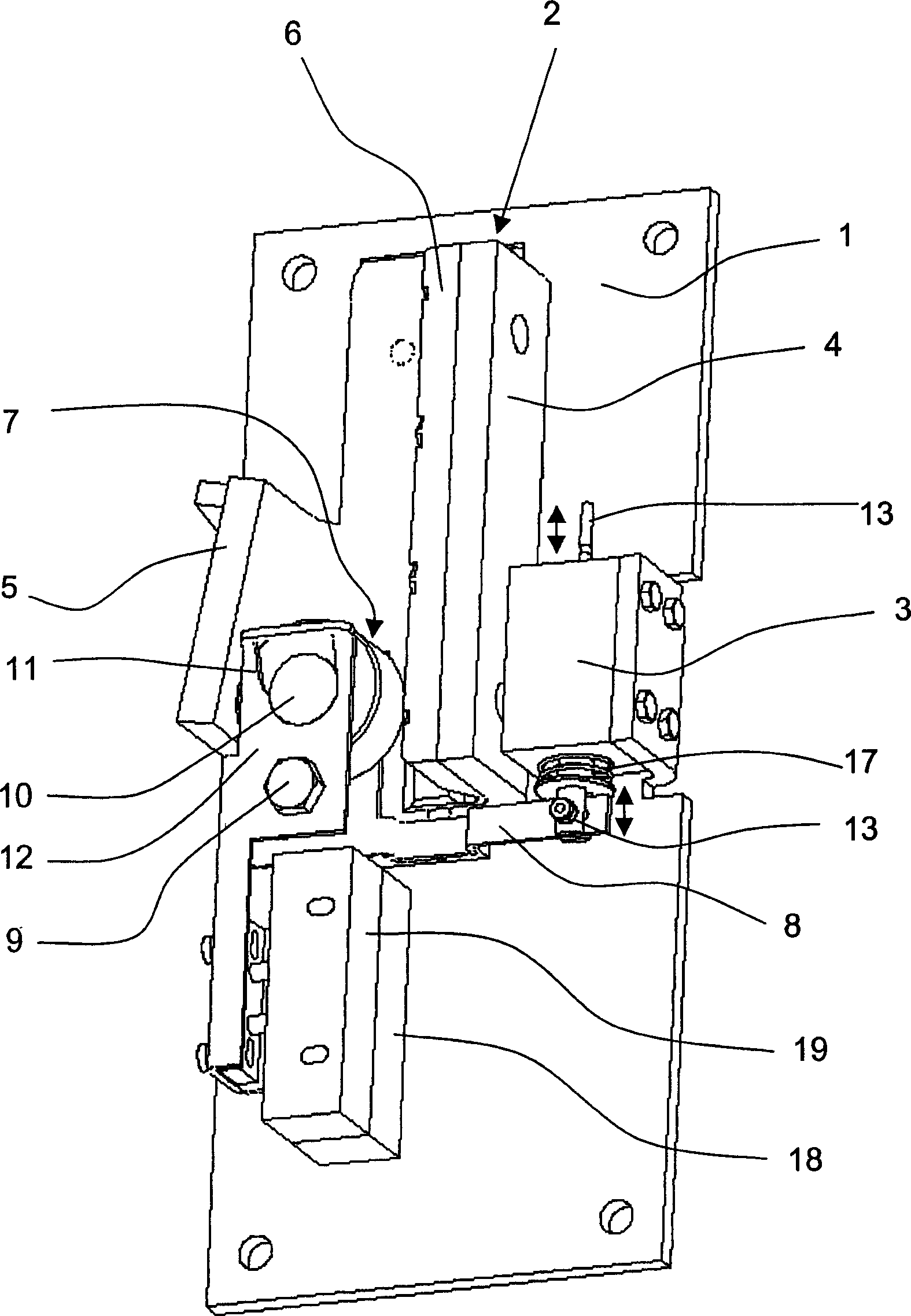
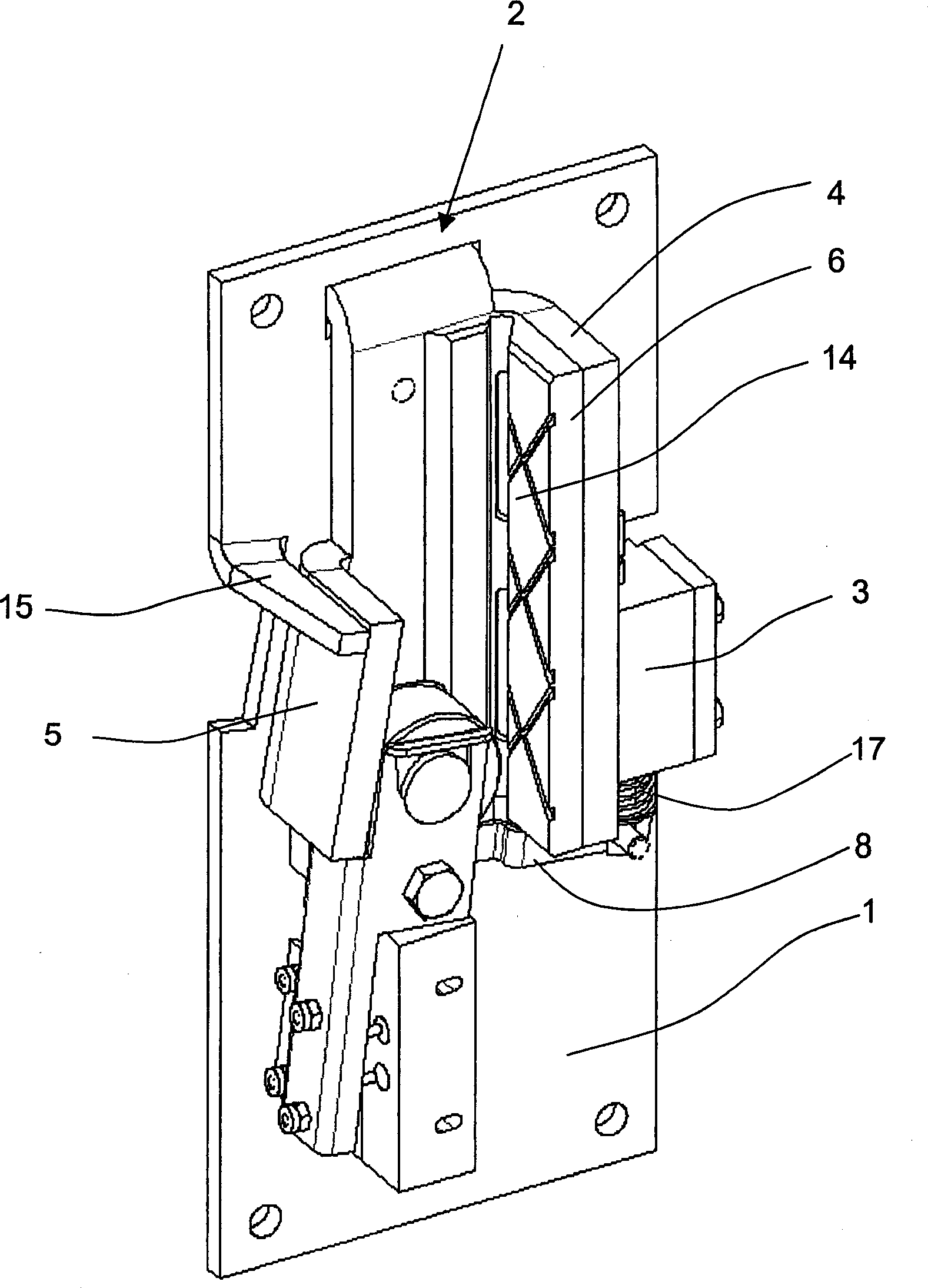
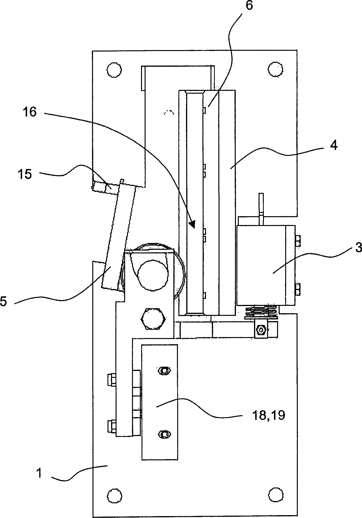
[0038] figure 1 A chassis 1 is shown, on which a safety brake housing 2 and an electromagnet 3 of the safety brake device are fixedly mounted. The safety brake housing 2 has a section with a U-shaped cross section formed by two flanges 4 and 5 , wherein the inside of the flange 4 is provided with a guide and brake lining 6 . The safety braking device is installed on the elevator car of the elevator system, and the safety braking device is connected with the guide rail 30 for guiding the car (see Figure 14 ) fit, that is, the guide flange 31 of the guide rail 30 (see Figure 4 with 14 ) is arranged between the guide and the brake lining 6, which is designed as a brake roller 7 in the present embodiment.

[0039] In operation, the guide and brake lining 6 is in contact with the guide surface 32 of the guide flange 31 . The flange 4 together with the guide and brake lining 6 forms an elongated holder for the guide flange 31 . With this safety brake, the car can be held or b...


PUM


Abstract

This safety device serves for braking an elevator car in an elevator system provided with a guide rail having a rectangular guide flange. The safety device is provided with a holding device 1, which carries a retaining element 4, 6 and an abutment 5. The safety device is arranged in such a way that the guide flange is positioned between the retaining element 4, 6 and the abutment 5 in operation. A mechanism 8 is available which squeezes a braking member in the form of a blocking roller 7 between the guide flange and the abutment 5 when braking. The mechanism 8, cooperating with an electromagnet 3, exhibits a suspension 12. In such suspension, the braking member 7 is movably placed and can be moved in a controlled way between different positions assigned to different operation conditions of the safety device.

Description

technical field [0001] The invention relates to a safety braking device of an elevator for braking an elevator car of an elevator system having at least one guide rail with at least one elongated guide surface, wherein the safety braking device comprises The holder and the support, the brake member is located on the guide surface between the holder and the support, and has a mechanism that makes the brake member in the braking position when braking the car. The brake element is clamped between the guide surface and the support when the element is in the braking position. Background technique [0002] For guiding the car of an elevator with guide rails, guide shoes arranged on the elevator car are used, which can be designed both as roller guide shoes and as sliding guide shoes. In the first case, the rollers usually have a so-called two-dimensional or three-dimensional guiding function, said rollers rolling on corresponding guide surfaces of the guide rail. In the second c...

Claims


Application Information

Patent Timeline
Patent Type & Authority Applications(China)
IPC IPC(8): B66B5/18B66B7/04
CPCB66B7/046B66B5/18
Inventor 克里斯托夫·利贝特劳鲁埃迪·斯托克埃斯本·罗特伯尔
Owner INVENTIO AG
Why Eureka
Try Eureka