Motor driver and its driving control system

A motor driver, drive control technology, applied in the direction of motor control, AC motor control, control system, etc., can solve the problem of increasing the cost of the motor driver

Inactive Publication Date: 2004-04-28
PANASONIC CORP
View PDF1 Cites 18 Cited by
  • Summary
  • Abstract
  • Description
  • Claims
  • Application Information

AI Technical Summary

Problems solved by technology

[0009] As described above, in the conventional sensorless position type sine wave driving technique implemented by estimating the induced voltage, at least two current detection elements such as current sensors must be used to detect the phase current in the motor to be driven, which increases the cost of manufacturing the motor drive

Method used


Image

  • Motor driver and its driving control system
  • Motor driver and its driving control system
  • Motor driver and its driving control system

Examples


Embodiment 1

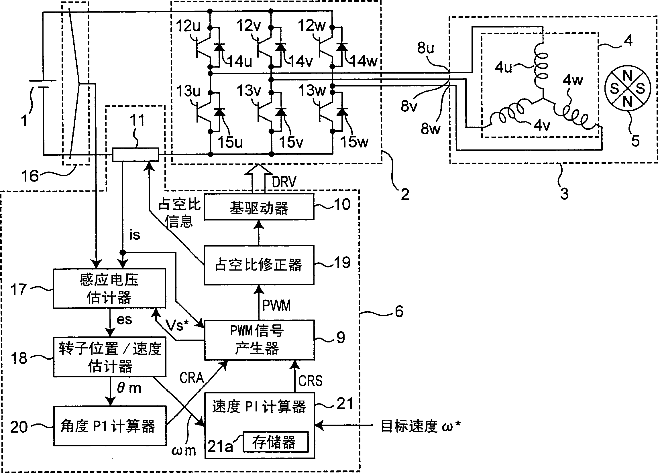
[0029] figure 1 A configuration diagram showing a combined system of a motor driver and a motor according to Embodiment 1 of the present invention. exist figure 1 Among them, reference numeral 1 denotes a DC power supply, 2 denotes an inverter, 3 denotes a brushless motor, 4 denotes a stator, 5 denotes a rotor, and 6 denotes a controller. The brushless motor 3 includes a stator 4 having three-phase windings 4u, 4v and 4w connected at a midpoint Y as a central point, and a rotor 5 loaded with magnets having magnetic poles N and S. The U-phase terminal 8u is connected to the non-connection end of the U-phase winding 4u, that is, to the opposite side of the neutral point. Similarly, the V-phase terminal 8v and the W-phase terminal 8w are connected to the non-connection end of the V-phase winding 4v and the non-connection end of the W-phase winding 4w, respectively.

[0030] Three series circuits of the inverter 2 are connected in parallel to the U phase, the V phase, and the...


PUM


Abstract

Duty information of PWM signals output of the duty correcting portion 19 is applied to the current detector 11 which is provided on an inverter busbar. Thus, the current detector determines which phase current of the three phases is appearing on the inverter busbar with reference to the duty information while detecting an inverter busbar current. The detected phase current is then used in the estimate calculation of the induced voltage.

Description

technical field [0001] The present invention relates to motor drives and drive control systems for controlling drives such as brushless DC motors at arbitrary speeds. Background technique [0002] Recently, in a motor driver configured to drive a motor such as used in a compressor of an air-conditioning system, the need to reduce energy consumption has become increasingly necessary from the viewpoint of global environmental protection. As an energy-saving technology in electric motors, inverters are widely used in driving high-efficiency electric motors such as brushless DC motors at any number of revolutions. [0003] Further, as a motor driving technique, a sine wave driving technique using a sinusoidal waveform is attracting attention because of its high efficiency and low noise, instead of a rectangular wave driving technique using a rectangular waveform. [0004] In the case where a motor such as a compressor is used in an air-conditioning system, since it is diffi...

Claims


Application Information

Patent Timeline
Patent Type & Authority Applications(China)
IPC IPC(8): H02P6/16H02P6/06H02P6/08H02P6/182H02P25/00
CPCH02P6/085H02P6/18H02P6/182H02P2209/09Y10S388/902Y10S388/906Y10S388/912Y10S388/9281
Inventor 野间博文松井敬三松城英夫后藤英二荒川政志竹内让
Owner PANASONIC CORP
Why Eureka
Try Eureka