Pushbutton device and operation method
A technology of buttons and electronic devices, which is applied in the input/output direction of user/computer interaction, and can solve problems such as increasing the difficulty of circuit design.
- Summary
- Abstract
- Description
- Claims
- Application Information
AI Technical Summary
Problems solved by technology
Method used
Image
Examples
Embodiment 1
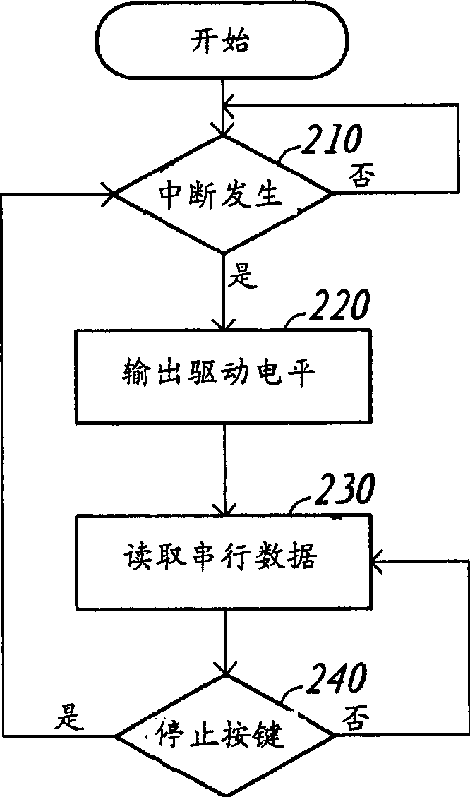
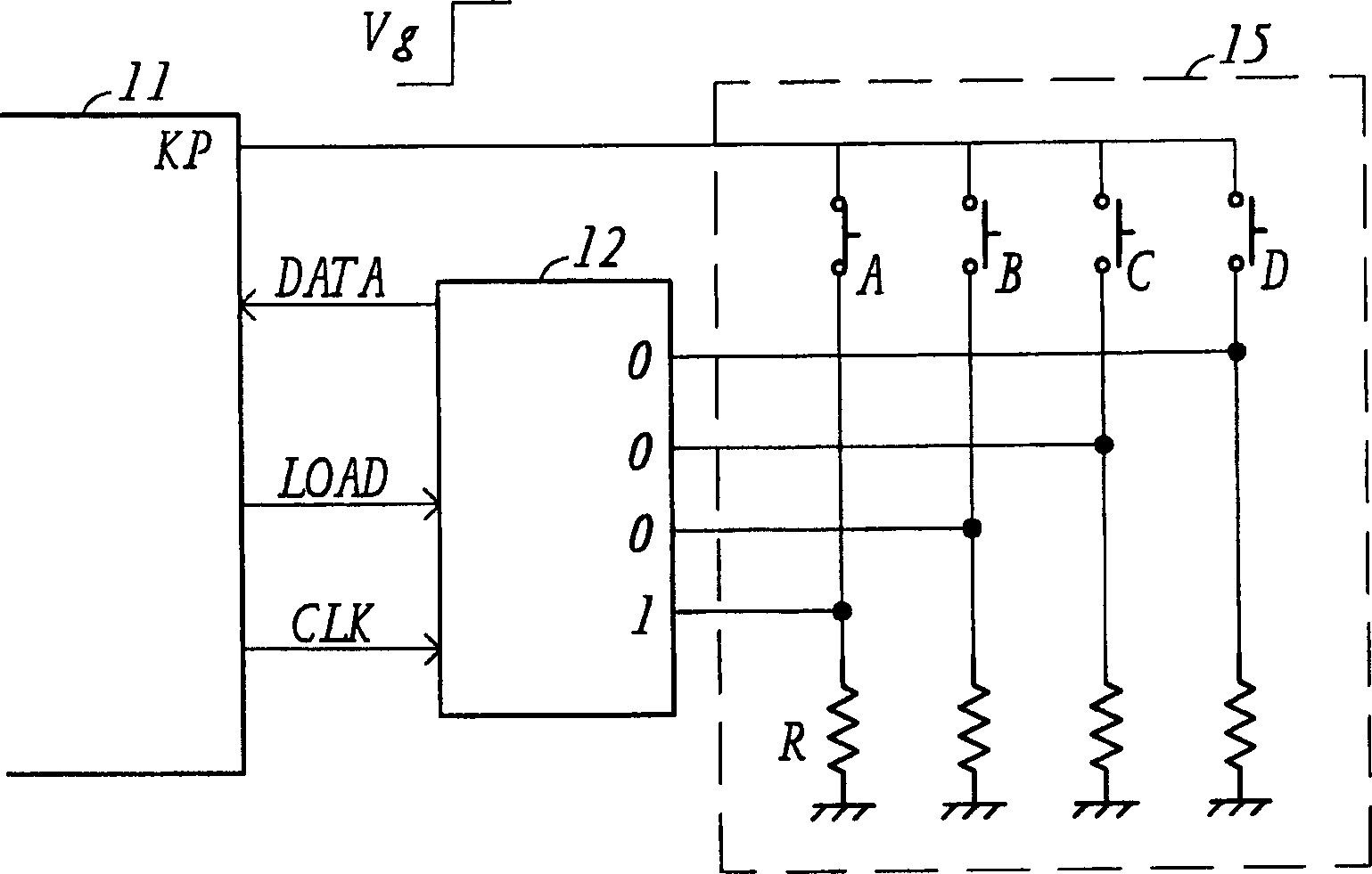
[0039] Please refer to figure 1 , which shows a block diagram of a key device provided according to a preferred embodiment of the present invention. The key device includes a parallel / serial conversion device 12 and a key module 15 for coupling to the controller 11 in an electronic device, such as a personal digital assistant. The buttons in the button module 15 are arranged in parallel, so as to have both expansibility and simplicity. Before the button module 15 is activated, the input / output pin KP of the controller 11 functions as an input pin. After the button module 15 is activated, an interrupt signal is fed into the input / output pin KP. After receiving the interrupt signal, the controller 11 converts the function of the input / output pin KP into an output pin, and feeds a driving potential into the key module 15 through the input / output pin KP, so that the key module 15 outputs a Parallel signal DP. Next, the controller 11 feeds the load signal LOAD into the parallel / ...
Embodiment 2
[0046] Then please refer to Figure 4, which shows a block diagram of a key device provided according to the second embodiment of the present invention. The key device includes a key module 45 , a conversion circuit 42 , a control circuit 411 and an identification circuit 415 , wherein the control circuit 411 and the identification circuit 415 can be provided in the microcontroller 41 . When a certain (or some) key in the key module 45 is pressed, the key module 45 outputs a low-level interrupt signal INT to the control circuit 411 . When the control circuit 411 receives the interrupt signal INT, it will feed a high-level driving potential DV into the conversion circuit 42, so that the conversion circuit 42 receives the bit data group BDP generated by the button module 45 in parallel, wherein the bit data The group BDP corresponds to the state in which the button module 45 is pressed, and may include several bits of data, for example, eight. After the conversion circuit 42 r...
PUM
 Abstract
Description
Claims
Application Information
 - R&D
- Intellectual Property
- Life Sciences
- Materials
- Tech Scout
- Unparalleled Data Quality
- Higher Quality Content
- 60% Fewer Hallucinations
Browse by: Latest US Patents, China's latest patents, Technical Efficacy Thesaurus, Application Domain, Technology Topic, Popular Technical Reports.
© 2025 PatSnap. All rights reserved.Legal|Privacy policy|Modern Slavery Act Transparency Statement|Sitemap|About US| Contact US: help@patsnap.com


