
Print head using radio-frequency micro-electromechanical system spary head

A micro-electromechanical system and print head technology, applied in printing, circuits, electrical components, etc., can solve problems such as low printing speed, complex structure, high integration of multiple nozzles, and unclear images

Inactive Publication Date: 2004-05-19
SAMSUNG ELECTRONICS CO LTD
View PDF1 Cites 5 Cited by
  • Summary
  • Abstract
  • Description
  • Claims
  • Application Information

AI Technical Summary

Problems solved by technology

[0009] The disadvantage of conventional inkjet printheads using the above-mentioned piezoelectric body is that the printing speed is low due to the limitation of the operating speed of the piezoelectric body.
Ink does not discharge or the output image is not clear under low temperature and humidity conditions
In addition, the problem with this print head is that it is difficult to precisely adjust the amount of ink discharged, and due to the limitation of the response speed of the thermistor, the ink discharge response speed is low.
Moreover, this type of print head also has the problem that the structure is too complicated to make a high degree of integration of multiple nozzles, thus further limiting the resolution of the output image.

Method used


Image

  • Print head using radio-frequency micro-electromechanical system spary head
  • Print head using radio-frequency micro-electromechanical system spary head
  • Print head using radio-frequency micro-electromechanical system spary head

Examples


Embodiment Construction

[0030] This application takes the entirety of Korean Patent Application No. 2002-63573 filed on October 17, 2002 and entitled "Printhead Using RF MEMS Head" as reference in its entirety.

[0031] Hereinafter, the present invention will be fully described with reference to preferred embodiments of the invention shown in the accompanying drawings. Of course, the present invention may be embodied in different forms and is not limited to the embodiments set forth herein. But precisely, these embodiments provided herein fully and fully disclose and completely express the concept of the present invention to those skilled in the art. In the drawings, the thicknesses of layers and regions are exaggerated for clarity. It will be understood that when a layer is referred to as being "on" another layer or substrate, it can be directly on the other layer or substrate, or intervening layers may also be present. Further, it will also be understood that when a layer is referred to as being ...


PUM


Abstract

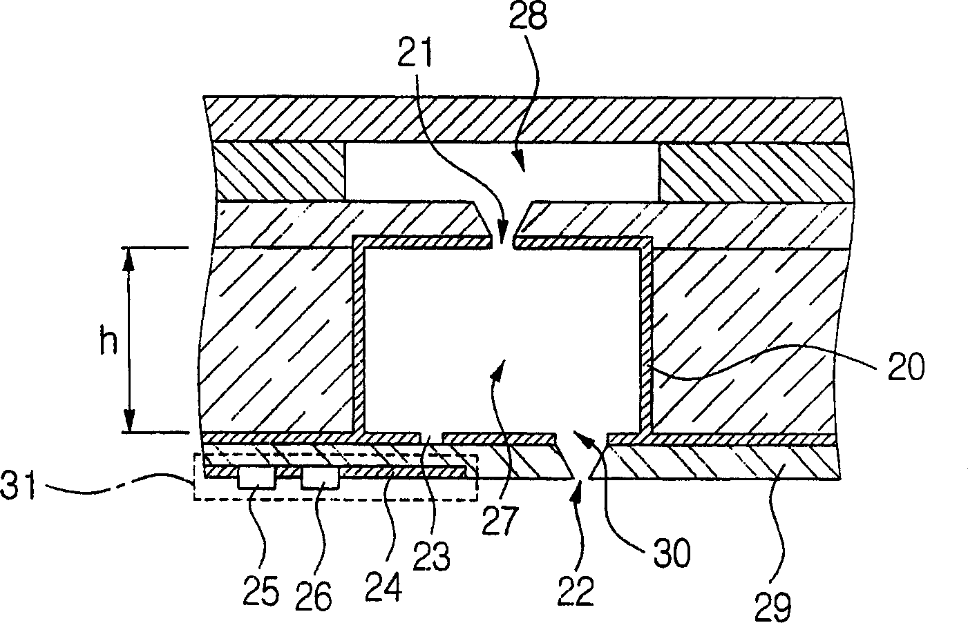
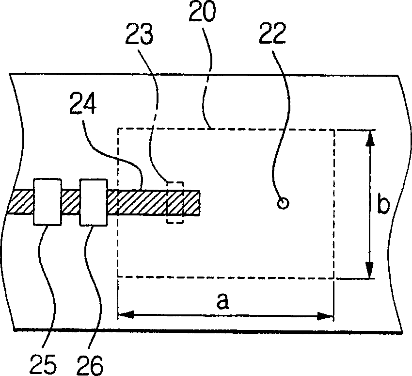
A printer head using a radio frequency micro-electromechanical system (RF MEMS) sprayer includes an inner pressure chamber having a liquid inlet and a liquid outlet; a cavity resonator surrounding the inner pressure chamber, wherein the cavity resonator inputs a predetermined cavity resonance frequency signal to increase an inner pressure of the inner pressure chamber; a signal transmitting unit for generating the predetermined cavity resonance frequency signal and for inputting the generated cavity resonance frequency signal into the inner pressure chamber through the cavity resonator in response to an external input control signal; and a liquid chamber for supplying a liquid, wherein the liquid inlet and the liquid outlet each extend through the inner pressure chamber and the cavity resonator so that when an inner pressure of the inner pressure chamber is increased by the cavity resonator, a liquid from within the inner pressure chamber is ejected.

Description

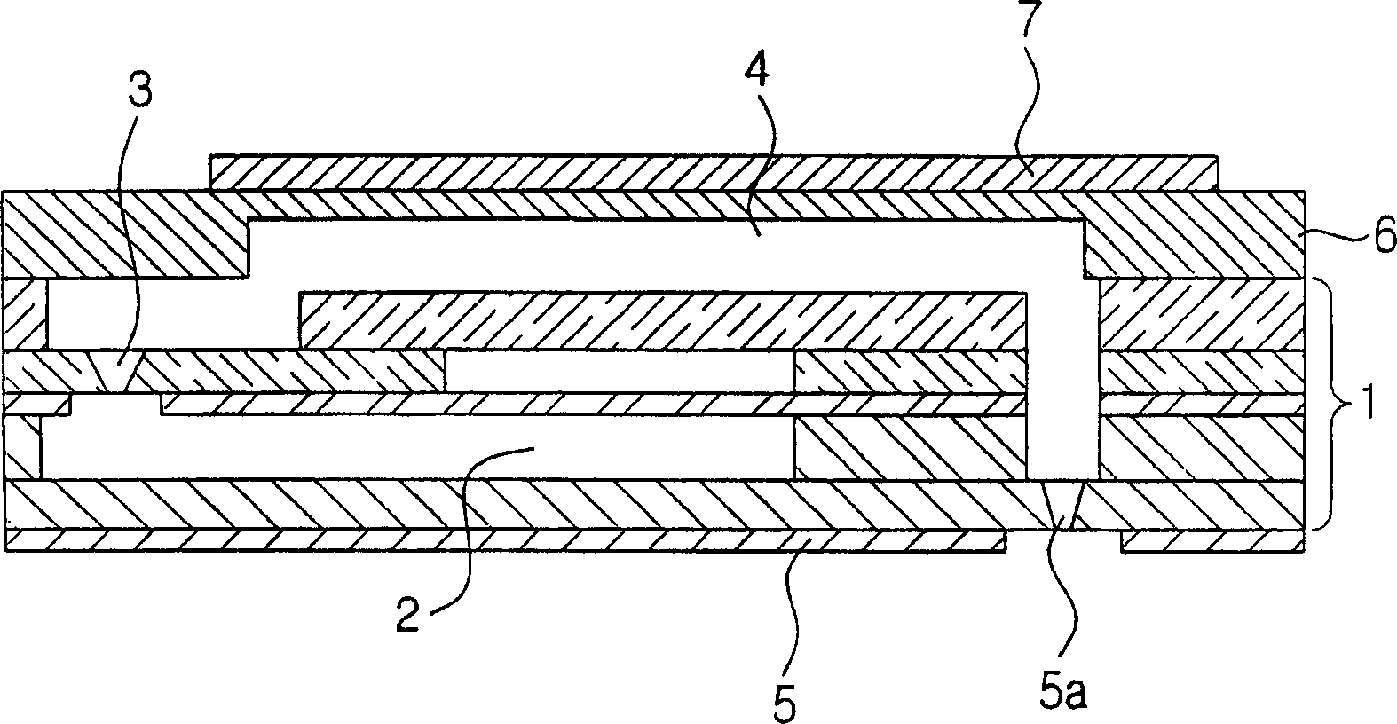
technical field [0001] The present invention relates to an inkjet printhead, and more particularly, to a printhead using a radio frequency microelectromechanical system (RF MEMS) printhead including a radio frequency (RF) cavity resonator. Background technique [0002] In general, an ejection device for ejecting liquid droplets may be used in inkjet print heads, MEMS cooling devices, and the like. The driving method for the inkjet print head can be classified into a mechanical driving method using a piezoelectric element or a thermal driving method. [0003] figure 1 A cross-sectional view showing a conventional printhead using piezoelectric elements. [0004] like figure 1 As shown, a conventional print head using piezoelectric elements includes a plate-shaped piezoelectric body 7, and a vibrating plate 6 arranged below the piezoelectric body 7 for converting the longitudinal extension motion of the piezoelectric body 7 into a bending motion is arranged on the The liqui...

Claims


Application Information

Patent Timeline
Patent Type & Authority Applications(China)
IPC IPC(8): B41J2/015B41J2/045B41J2/135B41J2/14B41J2/235B81B7/00
CPCB41J2/14008B41J2/235
Inventor 宋寅相
Owner SAMSUNG ELECTRONICS CO LTD
Learn More