Gasified burner of heating device driven by liquid state fuel

A technology of liquid fuel and heating device, which is applied to gas fuel burners, burners using capillary action, burners, etc., can solve the problem of expensive manufacturing of fuel diffusion devices, and achieve the effect of uniform and good distribution

Active Publication Date: 2004-05-26
韦贝斯托热系统有限公司
View PDF4 Cites 5 Cited by
  • Summary
  • Abstract
  • Description
  • Claims
  • Application Information

AI Technical Summary

Problems solved by technology

But such fuel diffusers are relatively expensive to manufacture

Method used


Image

  • Gasified burner of heating device driven by liquid state fuel
  • Gasified burner of heating device driven by liquid state fuel

Examples


Embodiment Construction

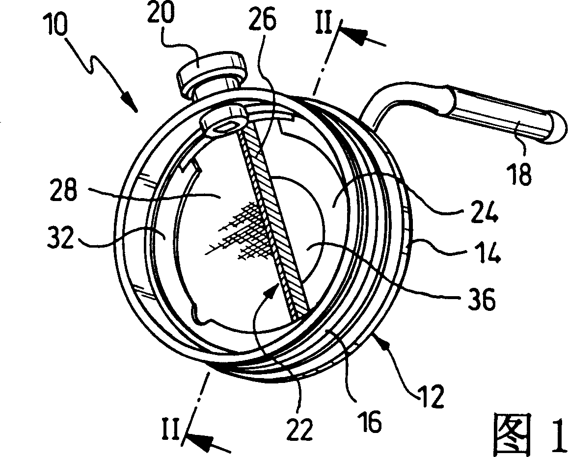
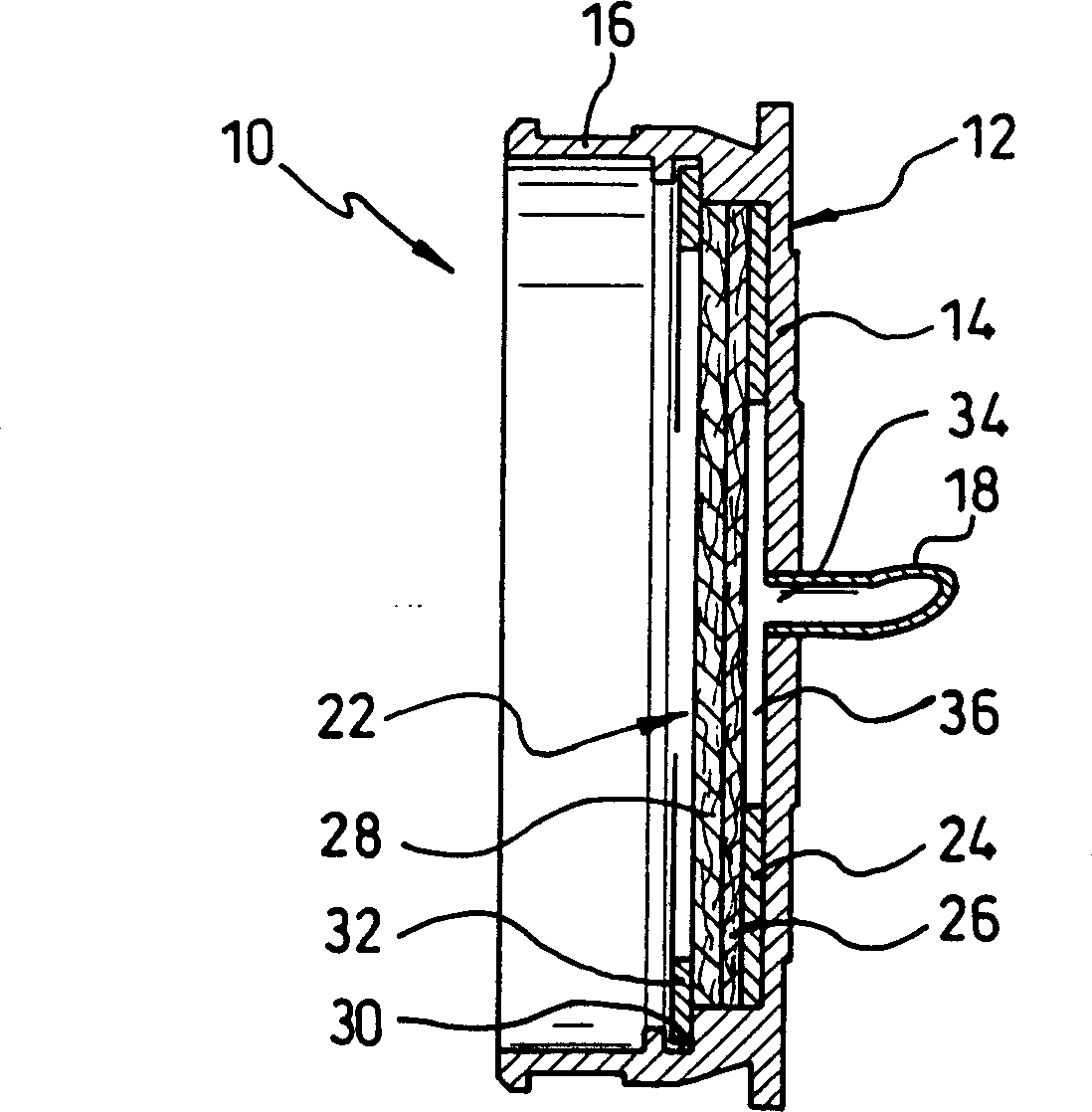
[0023] 1 and 2 show an evaporator burner 10 for a heating system of a permanent air-conditioning system of a passenger car, without the other parts being shown.

[0024] The gasification burner 10 is provided with a support part 12 consisting of a substantially disc-shaped rear wall 14 and an annular wall 16 rising therefrom.

[0025] A fuel feed line 18 for liquid fuel terminates on the rear wall 14 on the side facing away from the annular wall 16 .

[0026] The annular wall 16 stands substantially perpendicular to the rear wall 14 on the outer circumference of the rear wall 14 . A support 20 is formed on the annular wall 16 for mounting a flame observer / hot probe (Glühstift), not shown. A suction element 22 is arranged inside the annular wall 16 .

[0027] During operation of the gasification burner 10 , liquid fuel is supplied to the adsorbent element 22 via the fuel supply line 18 and through the rear wall 14 . The fuel is vaporized and burned in and on the adsorptive e...


PUM


Abstract

This evaporation burner 10 for a heating apparatus comprises a support member 12 having an absorbing element 22 and a fuel supply pipe 18 for supplying liquid fuel to the absorbing element 22, and is operated by the liquid fuel. The absorbing element 22 is formed of a layer 24 made of ceramic material and layers 26 and 28 made of metal material.

Description

technical field [0001] The invention relates to a gasification burner for a heating device driven by a liquid fuel, in particular as an additional heating device for a motor vehicle (Fahrzeugzuheizgert) or as a permanent heating device for a motor vehicle (Fahrzeugstandheizgert), which has a support A part on which an adsorbing element is arranged and a fuel feed conduit for introducing liquid fuel into said absorbing element. Furthermore, the invention relates to a heating device provided with such a gasification burner. Background technique [0002] DE 198 48 149 A1 discloses a burner of a motor vehicle heating system of the mentioned type, in which an adsorption body is arranged on the carrier part. Liquid fuel is fed to the sorbent body through a fuel feed conduit. Fuel will be distributed in or on the sorbent body and vaporized. The vaporized fuel is burned in a combustion chamber which is formed in front of the carrier part and the sorbent body. The problem arise...

Claims


Application Information

Patent Timeline
Patent Type & Authority Applications(China)
IPC IPC(8): B60H1/03F23D3/40
CPCF23D3/40
Inventor 弗郎克·沙腾贝格贝恩特·道尔格纳
Owner 韦贝斯托热系统有限公司
Why Eureka
Try Eureka