Semiconductor laser light output stabilizing circuit and light transmitting module

A technology for stabilizing circuits and lasers, used in semiconductor lasers, lasers, laser parts, etc., and can solve the problems of reduced receiving sensitivity, increased extinction ratio, and deterioration of dispersion compensation characteristics.

Inactive Publication Date: 2004-05-26
KK TOSHIBA
View PDF1 Cites 9 Cited by
  • Summary
  • Abstract
  • Description
  • Claims
  • Application Information

AI Technical Summary

Problems solved by technology

[0023] In this way, there is a problem that on the high temperature side, the extinction ratio increases beyond the necessary value, and the emission line width of LD12 increases, resulting in deterioration of the dispersion compensation characteristic (which occurs when the optical signal obtained from LD12 is actually transmitted for several tens of kilometers with an optical fiber. resulting in reduced receiver sensitivity)
[0032] As mentioned above, there is a problem in the optical output stabilization circuit of the semiconductor laser in the past: when the semiconductor laser is high temperature, due to the saturation of the I-L characteristic, there is an excess pulse driving current, and the extinction ratio increases to more than the necessary value at high temperature.
[0033] In addition, the pilot signal detector in the optical output stabilization circuit of the conventional semiconductor laser has the problem that the amplitude of the pilot component must be increased beyond a certain level, resulting in the deterioration of the S / N of the emitted light and the reduction of the receiving sensitivity.

Method used


Image

  • Semiconductor laser light output stabilizing circuit and light transmitting module
  • Semiconductor laser light output stabilizing circuit and light transmitting module
  • Semiconductor laser light output stabilizing circuit and light transmitting module

Examples


no. 1 Embodiment approach

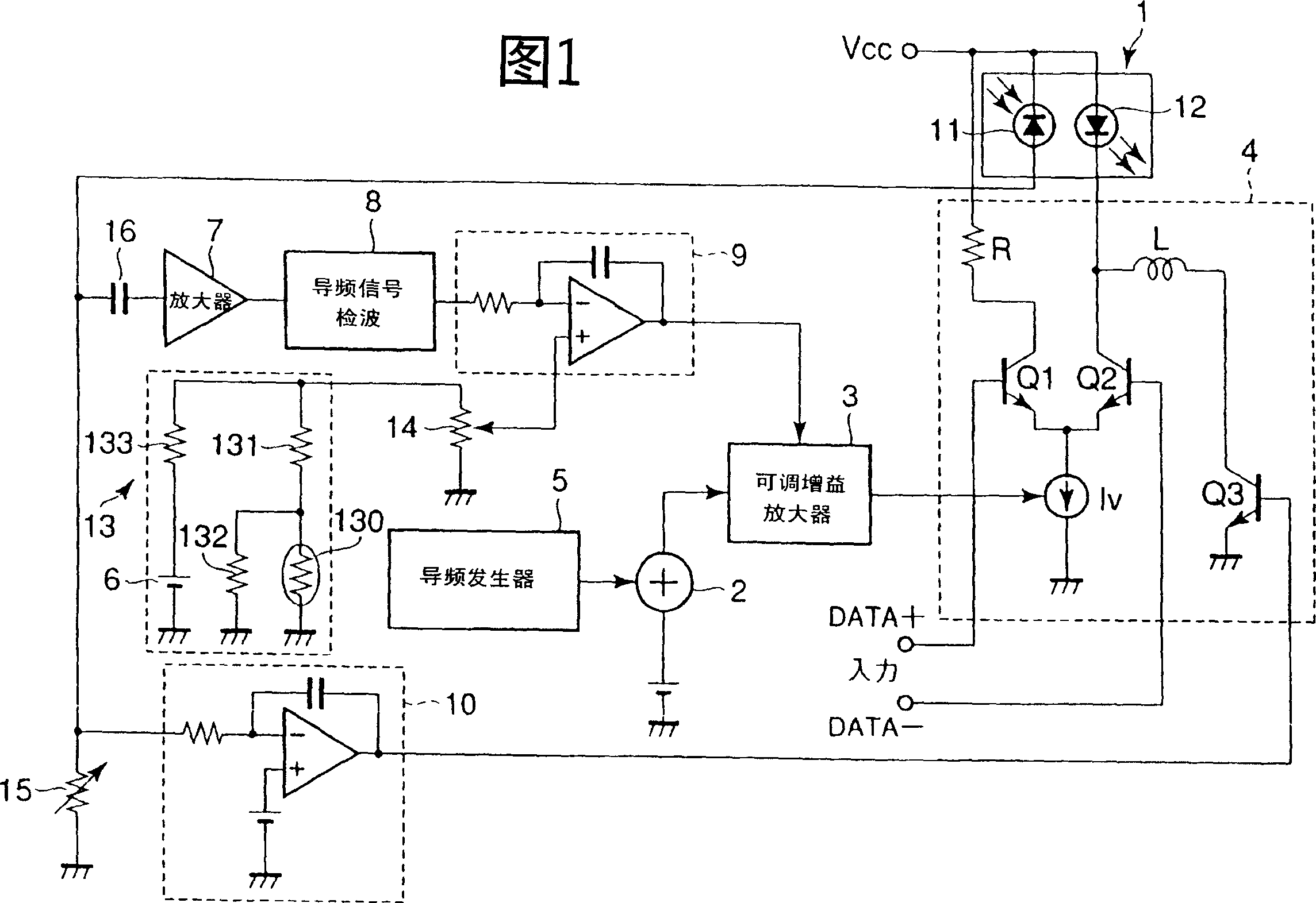
[0059] FIG. 1 is an explanatory diagram showing the configuration of an optical transmission module employing an optical output stabilization circuit according to a first embodiment of the present invention.

[0060] The optical transmission module shown in Figure 1, compared with the optical transmission module shown in Figure 6, is different in that the standard voltage of the first error amplifier 9 is temperature compensated (the higher the temperature, the lower the standard voltage) The temperature compensation circuit 13 reduces the variation of the extinction ratio of the laser output light during high temperature operation, and the others are the same, so the same symbols as those in FIG. 6 are marked.

[0061] In this module, a semiconductor laser module 1 incorporates an LD 12 and a monitoring photoelectric element (for example, a photodiode PD) 11 for detecting the optical output power of the LD 12 .

[0062] In the above optical output stabilization circuit, 2 is ...

no. 2 Embodiment approach

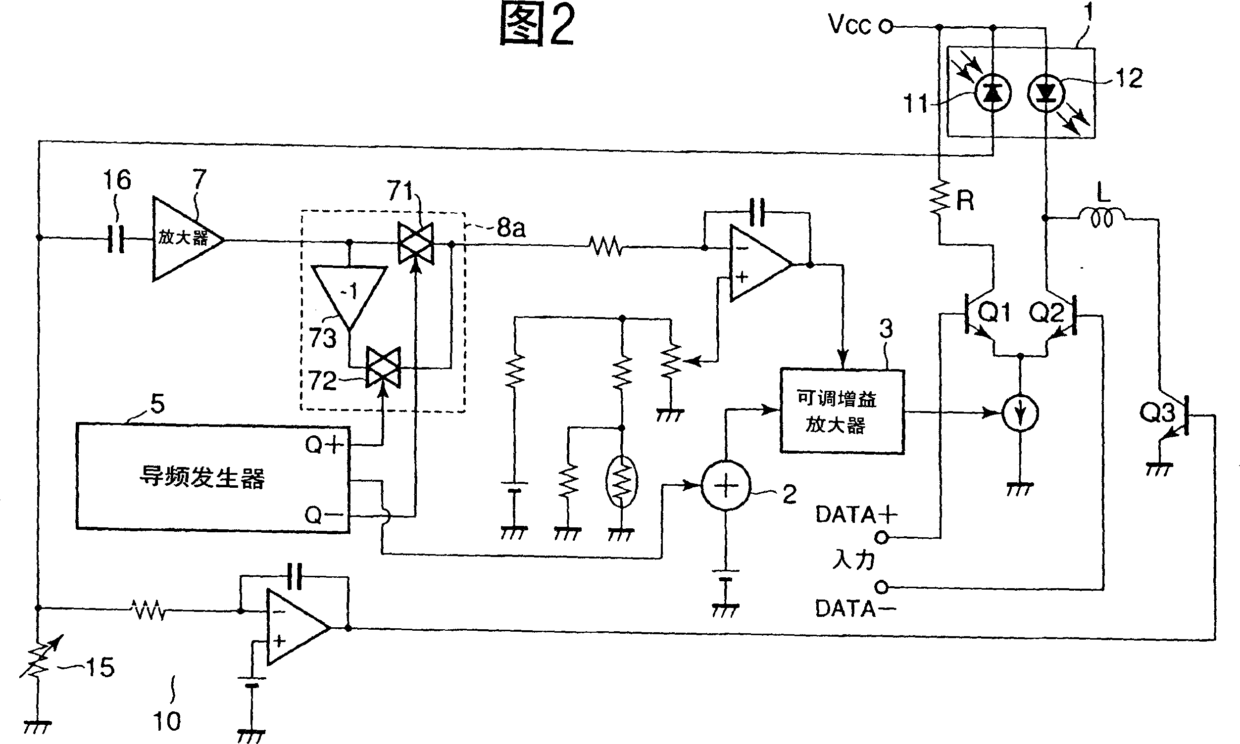
[0080] FIG. 2 is an explanatory diagram showing the configuration of an optical transmission module employing an optical output stabilization circuit according to a second embodiment of the present invention.

[0081] Compared with the optical transmission module shown in FIG. 1 , the optical transmission module shown in FIG. 2 is different in that a synchronous pilot signal detection circuit 8 a is used as the pilot signal detector 8 , and the others are the same.

[0082] The above-mentioned synchronous pilot signal detection circuit 8a can be realized with a simple structure by using a full-wave rectifier, including: using a clock signal synchronized with the pilot signal supplied by the pilot signal generator 5 to perform complementary ON / OFF operation A pair of analog switches 71, 72, and an inverting amplifier 73 for inverting one input of the analog switches 71, 72.

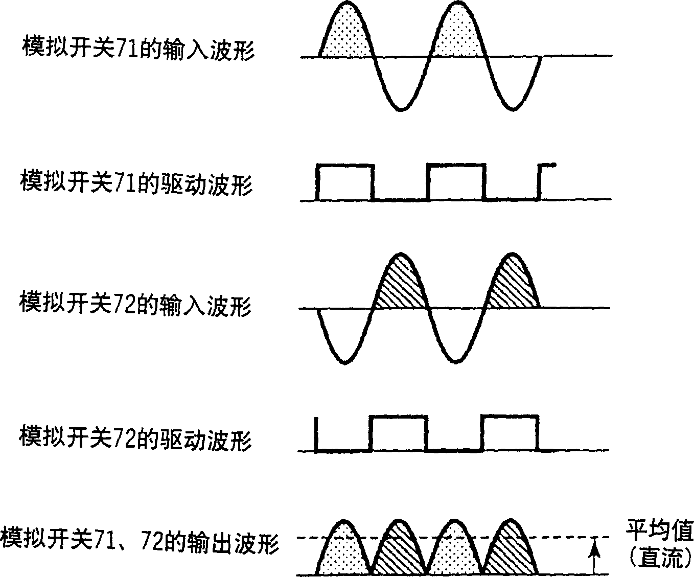
[0083] image 3 Operation waveforms of the synchronous pilot signal detection circuit in FIG. 2 are sh...

no. 3 Embodiment approach

[0087] In the third embodiment, a modified example of the control device for the laser driving pulse current of the pilot signal of the optical output stabilization circuit in the above-mentioned first and second embodiments will be described.

[0088] FIG. 4 shows the configuration of an optical transmission module using an optical output stabilization circuit according to a third embodiment of the present invention.

[0089] Compared with the optical transmission module shown in FIG. 1, the optical transmission module shown in FIG. 4 replaces the combination of the analog addition circuit 2 and the adjustable gain amplifier 3, and adopts such a laser driving pulse current control circuit 80, that is, It includes: inputting the output signal of the first error amplifier 9, an analog switch 81 for on / off operation by using a clock signal synchronized with the pilot signal supplied from the above-mentioned pilot signal generator 5, and inputting the output of the analog switch 8...


PUM


Abstract

To stabilize extinction ratio of laser output light over the whole operating temperature range by suppressing the extinction ratio of laser output light from being increased more than required, by restraining an excess pulse drive current from flowing due to the saturation of the slope efficiency in an I-L characteristic in high temperature operation of a semiconductor laser. In an optical output stabilizing circuit in which a modulation current is controlled by detecting the slope efficiency in an injection current versus an optical output characteristic of the semiconductor laser 12, a temperature-compensation circuit 13 for a reference voltage of a difference amplifier 9 is added to reduce fluctuation of the extinction ratio of laser output light in high temperature operation by compensating the saturation of the slope efficiency by temperature-compensating the reference voltage in an error amplifier.

Description

technical field [0001] The present invention relates to an optical output stabilizing circuit and an optical transmission module of a semiconductor laser, in particular to a circuit that can stabilize the extinction ratio of the laser output light without using a Peltier element or the like to stabilize the temperature of the semiconductor laser, such as for use in assembly In optical transmitters using semiconductor lasers in optical fiber transmission devices. Background technique [0002] In order to stabilize the extinction ratio of the output light of the semiconductor laser, the semiconductor laser is sometimes subjected to temperature stabilization treatment using a Peltier element or the like, but in order to reduce power consumption and cost, the temperature stabilization treatment is also sometimes not performed. [0003] In this way, without temperature stabilization, conventional optical output stabilization circuits used to optimally control the bias current and...

Claims


Application Information

Patent Timeline
Patent Type & Authority Applications(China)
IPC IPC(8): H01S3/13H01S5/068H01S5/0683
CPCH01S5/0683H01S5/06804
Inventor 谷越贞夫
Owner KK TOSHIBA
Why Eureka
Try Eureka