Passive optical fiber net of loop of multiple wave length light generated by utilizing central location

A passive optical network and multi-wavelength technology, applied in the field of optical communication systems, can solve the problems of increased transmission error rate, inability to operate high-capacity optical signal networks, and increased cost of user-side devices.

Inactive Publication Date: 2004-05-26
SAMSUNG ELECTRONICS CO LTD
View PDF0 Cites 2 Cited by
  • Summary
  • Abstract
  • Description
  • Claims
  • Application Information

AI Technical Summary

Problems solved by technology

[0015] However, when the conventional WDM passive optical fiber network uses a frequency-divided light source or a single-mode light source generated by locking a multimode laser diode as the light source for sending uplink optical signals, the sudden increase in the capacity of the uplink optical signal will cause high-capacity optical The transmission of the signal makes the network operation impossible, or causes the problem that the transmission error rate increases rapidly
Another problem is that when a single-mode laser diode such as DFB LD is used as a light source for transmitting upstream optical signals, the cost of constructing user-side devices increases

Method used


Image

  • Passive optical fiber net of loop of multiple wave length light generated by utilizing central location
  • Passive optical fiber net of loop of multiple wave length light generated by utilizing central location
  • Passive optical fiber net of loop of multiple wave length light generated by utilizing central location

Examples


Embodiment Construction

[0026] Preferred embodiments of the present invention will be described in detail below with reference to the accompanying drawings.

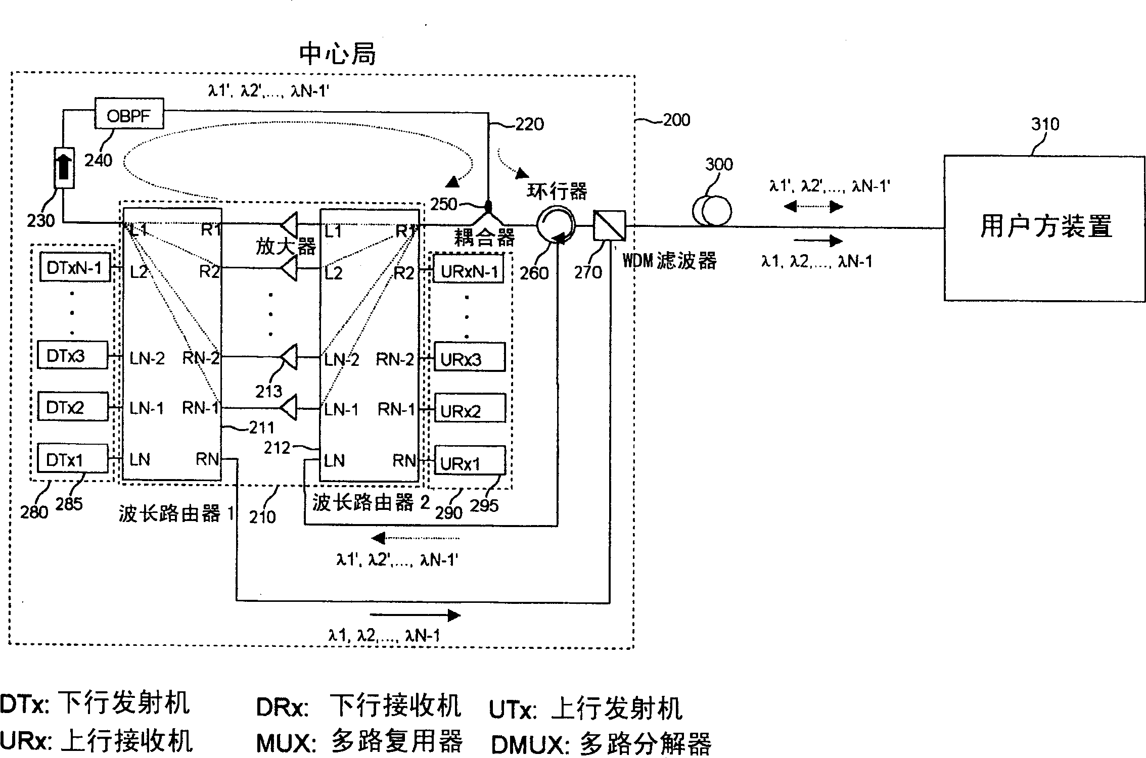
[0027] figure 2 The construction of a wavelength division multiplexing (WDM) passive optical fiber network according to the present invention is shown. The passive optical network includes a central office 200 and a customer side device 310, wherein the customer side device 310 is connected with the central office 200 through an optical fiber link 300, and performs communication with the central office 200 according to a wavelength division multiplexed optical signal.

[0028] The central office 200 transmits a downlink optical signal modulated with multi-wavelength light and a data signal to the user side device 310 and receives an uplink optical signal from the user side device 310 . The user side device 310 receives the multi-wavelength light and downlink optical signal from the central office 200, demultiplexes the multi-wavelength light ...


PUM


Abstract

A passive optical network includes a central office (200) and a subscriber-side apparatus (310) connected with the central office (200) through an optical fiber link (300). The subscriber-side apparatus (310) performs communication with the central office (200) based on wavelength-division-multiplexed optical signals. The central office has a routing section (210), provided with first to fourth multiplexing ports (L1,RN,LN,R1), for demultiplexing multi-wavelength light inputted from the fourth multiplexing port (R1) into a plurality of channels (L1,LN,1). Each of the demultiplexed channels (L1,LN,1) is amplified and multiplexed for output through the first multiplexing port (L1). Optical signals inputted through the third multiplexing port (LN) are demultiplexed and outputted upstream. The routing section also multiplexes channels for downstream optical signals, outputting the multiplexed channels through the second port (RN). A splitting section (250), provided with first to third splitting ports and arranged on a loop optical waveguide connects the first (L1) and fourth (R1) multiplexing port with each other. The splitting section (250) causes some of multi-wavelength light inputted into the first splitting port to be outputted through the second splitting port and causes the remainder of multi-wavelength light to be outputted through the third splitting port connected with the fourth multiplexing port (R1). A circulator (260) causes the multi-wavelength light inputted through the second splitting port to be transmitted to the subscriber-side apparatus (310) and causes upstream optical signals received from the subscriber-side apparatus (310) to be outputted to the third multiplexing port (LN).

Description

technical field [0001] The present invention relates to an optical communication system, more specifically, relates to a wavelength division multiplexing passive optical fiber network. Background technique [0002] A wavelength division multiplexing (WDM) passive optical network distributes optical signals downstream from the central office to each user. A remote node in the network between the central office and the subscribers, where active components are replaced by passive components such as amplifiers and transmitters. Likewise, upstream optical signals are sent to the central office along with user data through passive components. In this WDM passive optical network, both the central office and remote nodes need a device for multiplexing and / or demultiplexing uplink and downlink optical signals, and both the central office and users need transmitters and receivers. [0003] Recently, attempts have been made in WDM passive optical networks to efficiently implement a m...

Claims


Application Information

Patent Timeline
Patent Type & Authority Applications(China)
IPC IPC(8): H04B10/27H04B10/00H04B10/272H04J14/00H04J14/02H04L12/00H04Q11/00
CPCH04B10/2587H04J14/0246H04Q11/0067H04J14/0226H04J2014/0253H04J14/0221H04J14/025H04Q2011/0016H04L12/00
Inventor 金钟权黄星泽吴润济
Owner SAMSUNG ELECTRONICS CO LTD
Why Eureka
Try Eureka