
High pressure quick inflator

A fast, high-pressure technology, applied in the direction of liquid variable displacement machinery, machines/engines, mechanical equipment, etc., can solve the problems of no air intake, short service life, waste of metal materials, etc., to increase gas pressure and long service life , the effect of improving work efficiency

Inactive Publication Date: 2004-06-09
胡宏法 +1
View PDF0 Cites 5 Cited by
  • Summary
  • Abstract
  • Description
  • Claims
  • Application Information

AI Technical Summary

Problems solved by technology

Although the structure is simple, the leather cup is prone to upward air leakage during compression, which reduces the air pressure, and it often takes time and effort to inflate the air.
In addition, the structure of the traditional pump restricts its material except for the cup and the handle to only use the outer cylinder, base and cup rod made of metal, which wastes metal materials, and is easy to absorb moisture and rust, and the service life is short

Method used


Image

  • High pressure quick inflator
  • High pressure quick inflator
  • High pressure quick inflator

Examples


Embodiment Construction

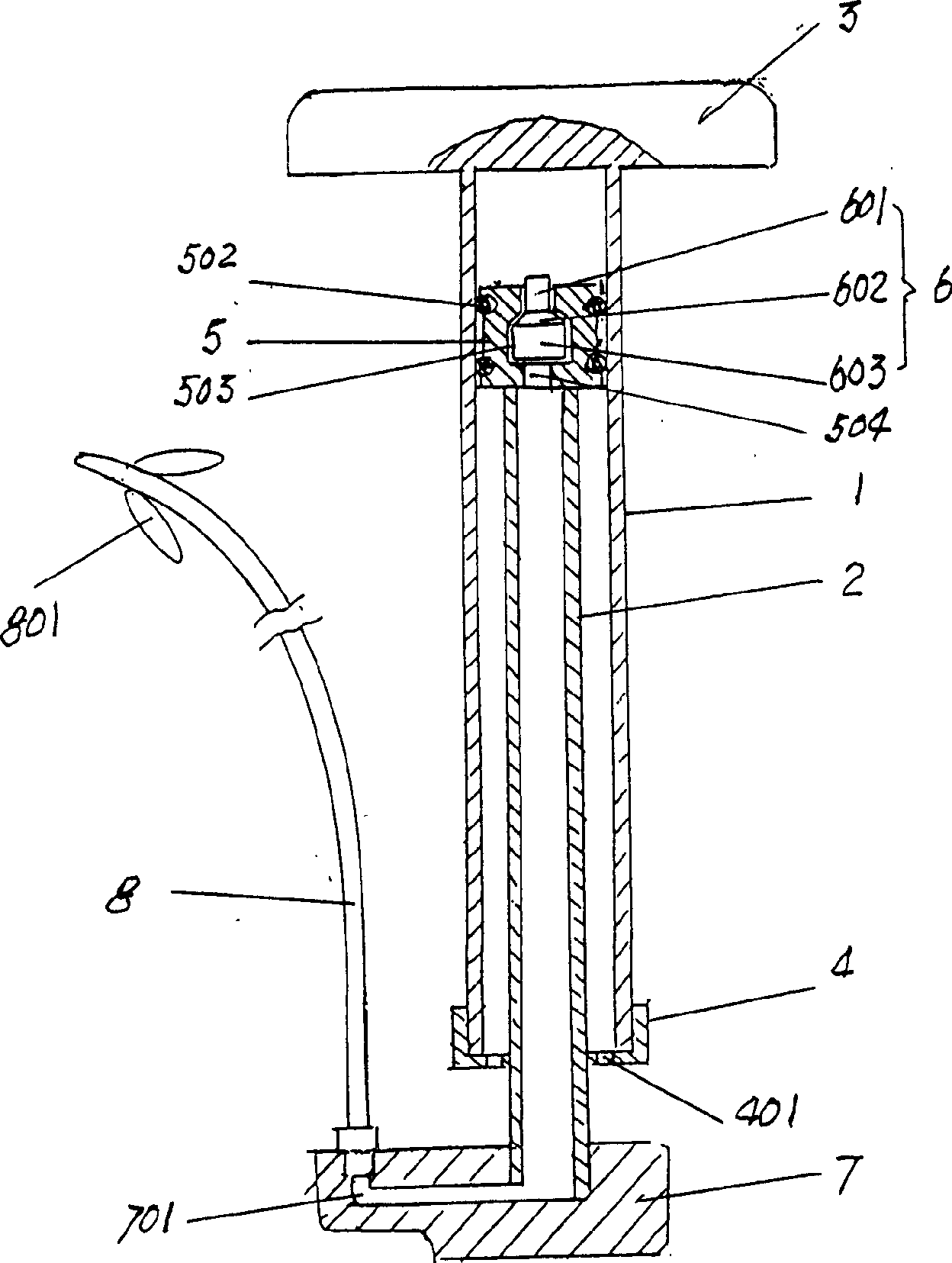
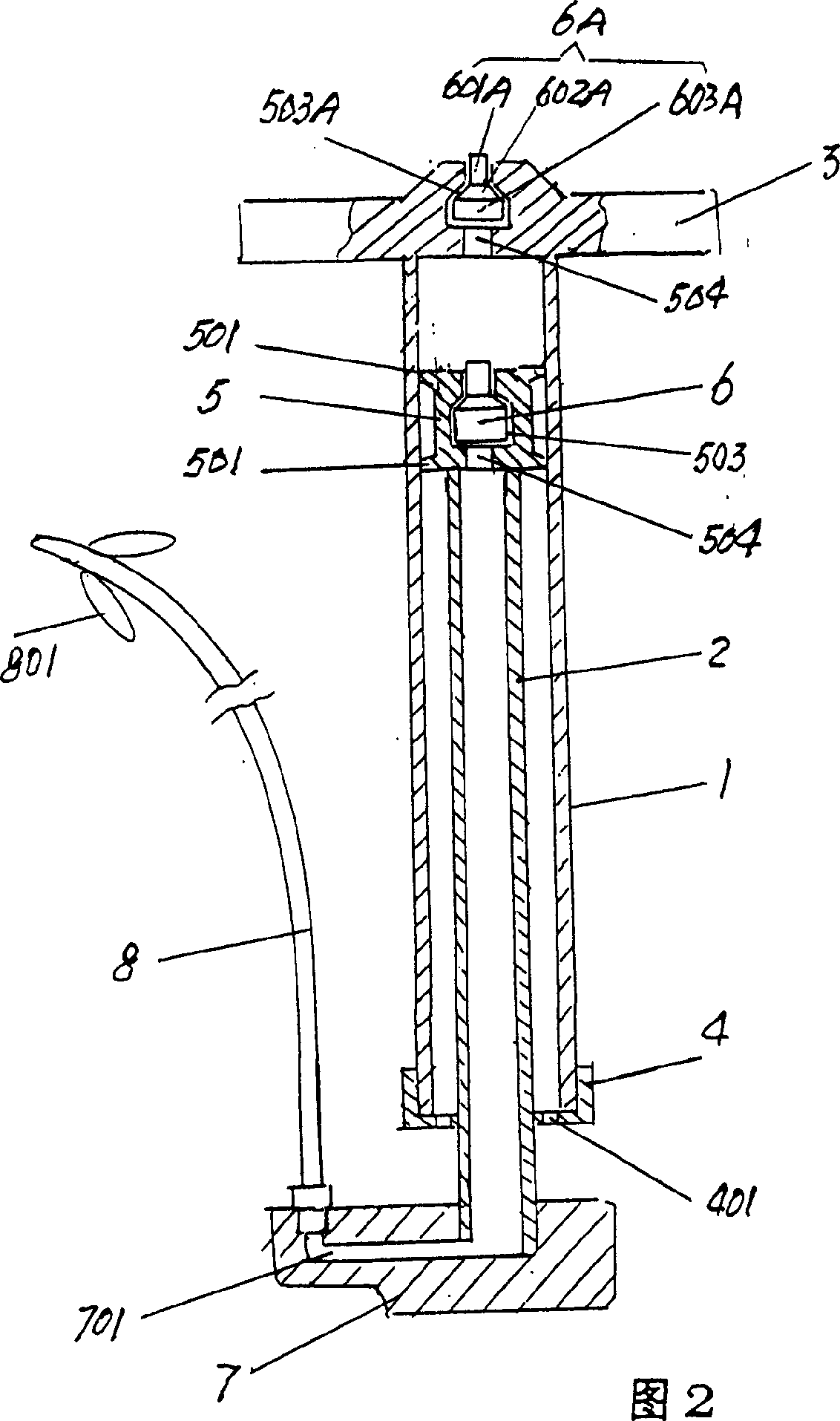
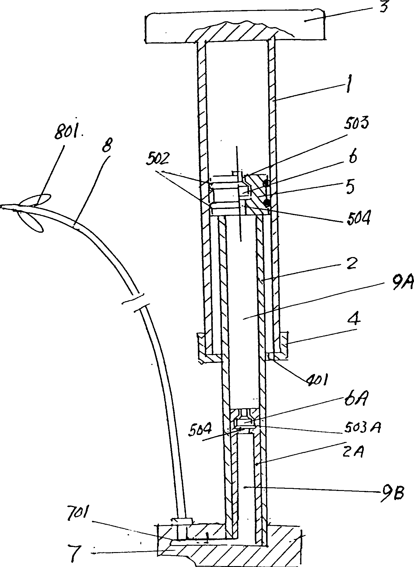
[0028] The accompanying drawings are numbered as follows:

[0029] 1. Outer cylinder

[0030] 2. Inner cylinder 2A. Second inner cylinder

[0031] 3. Pressure handle

[0032] 4. Cover 401. Air intake hole

[0033] 5. Piston seat

[0034] 501. Ring edge 502. O-ring 503. Inner cavity

[0035] 503A. Second lumen

[0036] 504. Gas channel 505. Disc 506. Thread

[0037] 507. Square vent

[0038] 6. Piston

[0039] 601. Guide column 602. Tapered surface 603. Cylinder

[0040] 6A. Second piston

[0041] 601A. Guide column 602A. Tapered surface 603A. Cylinder

[0042] 7. Base 701. Air outlet

[0043] 8. Hose 801. Air clip

[0044] 9A. First air bag 9B. Second air bag

[0045] Please refer to figure 1 , the present invention is a kind of high-pressure fast air pump, comprising a cylinder body, a piston and a pressure handle, the cylinder body has an outer cylinder 1 and an inner cylinder 2, the upper end of the outer cylinder 1 is connected to the pressure handle 3, and t...


PUM


Abstract

The present invention relates to a high-pressure quick bicycle pump. It includes pump body, piston and press-handle, said pump body has external tube and internal tube, the upper end of the external tube is connected with press-handle, and its lower end is equipped with a seal cover, said internal tube is placed in the internral cavity of the external tube, its upper end is connected with a piston seat, the periphery of said piston seat is equipped with two elastic sealing rings. The centre of said piston seat has a hollow cavity in which the piston in mounted, and said piston is formed from upper guide column, middle cone surface and lower cylinder which are connected into one body. Said invention can be made by using plastic components and its working efficiency is high.

Description

technical field [0001] The invention relates to an air cylinder for inflating vehicle tires. Background technique [0002] The air pump is used to inflate the tires of the vehicle, and it is a tool that both non-motor vehicles and motor vehicles must be equipped with. Traditional inflators use a leather cup as a piston, and the mouth of the cup is downwards. Using the elastic change of the cup, the cup goes up to inflate, and the cup goes down to compress the air. Although the structure is simple, the leather cup tends to leak upwards when the air is compressed, which reduces the air pressure, and it often takes time and effort to inflate the air. In addition, the structure of the traditional pump restricts its material except for the cup and the handle to only use the outer cylinder, base and cup rod made of metal, which wastes metal materials, is easy to absorb moisture and rust, and has a short service life. Contents of the invention [0003] The purpose of the presen...

Claims


Application Information

Patent Timeline
IPC IPC(8): F04B33/00
Inventor 胡宏法陈连冲
Owner 胡宏法
Learn More