
Method for controlling heating temp of microwaven oven

A technology of heating temperature and control method, which is applied to electric heating fuel, lighting and heating equipment, household heating, etc., can solve problems such as poor cooking effect and air-drying of food, shorten driving time, reduce air volume, and reduce external temperature The effect of reducing the rise

Inactive Publication Date: 2004-06-09
LG ELECTRONICS (TIANJIN) APPLIANCES CO LTD
View PDF0 Cites 7 Cited by
  • Summary
  • Abstract
  • Description
  • Claims
  • Application Information

AI Technical Summary

Problems solved by technology

As a result, the surface of the food will dry out, and the cooking effect will not be good.
[0012] This shows that above-mentioned existing microwave oven heating temperature control method still has many defectives, and needs to be improved

Method used


Image

  • Method for controlling heating temp of microwaven oven
  • Method for controlling heating temp of microwaven oven
  • Method for controlling heating temp of microwaven oven

Examples


Embodiment Construction

[0032] Below in conjunction with the accompanying drawings and preferred embodiments, the specific implementation, structure, features and effects of the present invention will be described in detail as follows.

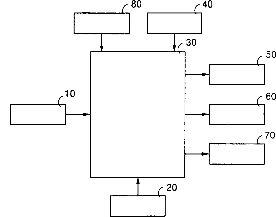
[0033] 10. Keyboard input unit 20. Power supply unit

[0034] 30. Control unit 40. Timer

[0035] 50. Grill heater 60. Convection heater

[0036] 70. Fan motor 80. Temperature sensing part

[0037] figure 2 It is a control structure diagram inside the heating chamber of the microwave oven of the present invention.

[0038] As shown in the figure, the microwave oven of the present invention generally includes a keyboard input unit 10 , a power supply unit 20 , a temperature sensing unit 80 , a timer 40 , a grill heater 50 , a convection heater 60 , a fan motor 70 and a control unit 30 . The above-mentioned keyboard input part 10 is used for inputting the cooking signal; the above-mentioned power supply part 20 is used for supplying power; the above-mentioned temp...


PUM


Abstract

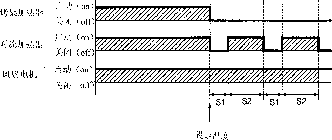
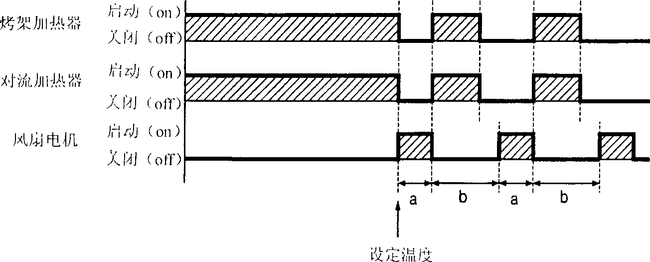
The heating temp. control method for microwave oven includes three stages: fan motor driving stage, starting from that internal temp. of heating chamber is reached to set pre-heating temp. driving fan motor in first specific period of time; heater driving stage, after the fan motor driving stage is completed, taking drive stop of fan motor as starting point, simultaneously driving grill heater and convection heater in second specific period of time; and repeated execution stage, according to the cooking time inputted by user repeatedly executing the above-mentioned two stages to heat food uniformly.

Description

technical field [0001] The present invention relates to a method for controlling the heating temperature of a microwave oven, more specifically, an invention about a method for controlling the heating temperature of a microwave oven that heats the heating chamber by controlling a fan motor and a heater in a convection mode microwave oven. Background technique [0002] Generally, a microwave oven is a device for heating food through microwaves. A magnetron (magnetron) is arranged in the electric control room, and the above-mentioned magnetron generates microwaves to irradiate the inside of the cooking chamber; the bottom surface of the above-mentioned cooking chamber is provided with a tray for placing cooking containers. In addition, the lower part of the tray is provided with a tray motor for rotating the tray. Then the food placed on the tray rotates together with the tray, so that the microwave irradiated in the cooking chamber can be evenly transmitted to the food in the...

Claims


Application Information

Patent Timeline
IPC IPC(8): F24C7/02F24C7/08
Inventor 金圭英
Owner LG ELECTRONICS (TIANJIN) APPLIANCES CO LTD
Learn More