
Pattern forming method of a semiconductor structure

A semiconductor and graphics technology, applied in semiconductor/solid-state device manufacturing, electrical components, circuits, etc., can solve the problems of photoresist collapse CD accuracy, etc., to reduce photoresist collapse, reduce bottom residue problems, and prevent pattern damage Effect

Active Publication Date: 2020-08-04
CHANGXIN MEMORY TECH INC
View PDF6 Cites 0 Cited by
  • Summary
  • Abstract
  • Description
  • Claims
  • Application Information

AI Technical Summary

Problems solved by technology

[0005] In view of the above-mentioned shortcomings of the prior art, the object of the present invention is to provide a method for forming a pattern of a semiconductor structure, which is used to solve the photoresist collapse caused by too thick photoresist layer and the accuracy of CD in the prior art. And other issues

Method used


Image

  • Pattern forming method of a semiconductor structure
  • Pattern forming method of a semiconductor structure
  • Pattern forming method of a semiconductor structure

Examples


Embodiment Construction

[0058] Embodiments of the present invention are described below through specific examples, and those skilled in the art can easily understand other advantages and effects of the present invention from the content disclosed in this specification. The present invention can also be implemented or applied through other different specific implementation modes, and various modifications or changes can be made to the details in this specification based on different viewpoints and applications without departing from the spirit of the present invention.

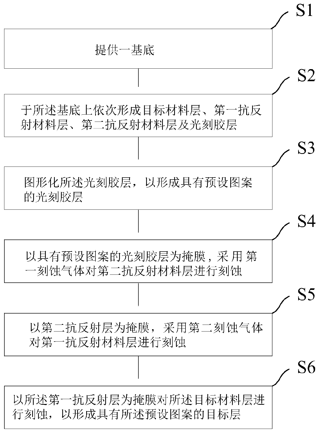
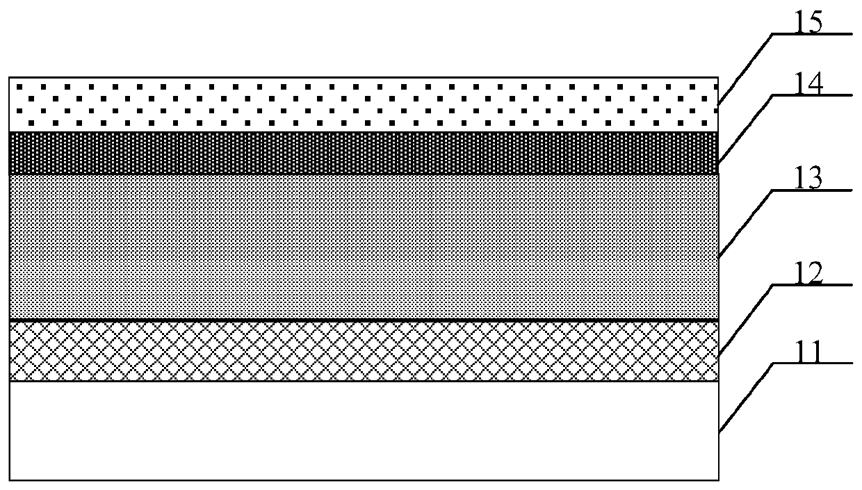
[0059] see Figure 1 to Figure 13 . It should be noted that the diagrams provided in this embodiment are only schematically illustrating the basic concept of the present invention, although only the components related to the present invention are shown in the diagrams rather than the number, shape and Dimensional drawing, the shape, quantity and proportion of each component can be changed arbitrarily during actual implementation, and...


PUM

PropertyMeasurementUnit
heightaaaaaaaaaa
heightaaaaaaaaaa
heightaaaaaaaaaa

Abstract

The invention provides a method for forming a pattern of a semiconductor structure which includes providing a substrate, a target material layer, a first antireflective material layer, a second antireflective material layer and a photoresist layer, all of which are orderly formed. The photoresist layer is patterned to form a preset pattern. A photoresist layer having a preset pattern is taken as amask. A second antireflective material layer is etched by using a first etching gas. A first etch gas includes a photoresist etch mitigation gas, so that the etching selection ratio of the second antireflective material layer to the photoresist layer is greater than 3: 1. The first antireflective material layer is etched by using the second etching gas with the second antireflective layer as a mask, and the target material layer is etched by using the first antireflective layer as a mask to form the target layer with a preset pattern. By adopting the scheme, the semiconductor structure forming method of the invention can reduce the aspect ratio of the photoresist layer, effectively reduces the divergence degree, increases the exposure accuracy, and prevents the pattern damage phenomenon caused by the photoresist residue.

Description

technical field [0001] The invention belongs to the technical field of semiconductor manufacturing, in particular to a pattern forming method of a semiconductor structure. Background technique [0002] In the semiconductor manufacturing process, a photoresist layer (PR) and a middle mask layer are often used to copy the required pattern into the device to form the actual required semiconductor structure. In practice, in order to increase the effectiveness of photolithography, various antireflective coatings are usually coated under the photoresist layer, such as bottom antireflective coating (BARC), and the BARC layer under the photoresist layer (photoresist layer) can be Reduce the reflection of light on the lower surface of the photoresist during the exposure process, so that most of the energy of the exposure is absorbed by the photoresist. For uniform exposure of the photoresist, the more preferred material is an anti-reflection layer based on Si. Or Si-ARC. [0003] A...

Claims


Application Information

Patent Timeline
Patent Type & Authority Patents(China)
IPC IPC(8): H01L21/3213H01L21/311
CPCH01L21/31116H01L21/31138H01L21/31144H01L21/32135H01L21/32139
Inventor 不公告发明人
Owner CHANGXIN MEMORY TECH INC
Learn More