
Hybrid contact structure with low aspect ratio contacts in a semiconductor device

a contact structure and semiconductor technology, applied in semiconductor devices, semiconductor/solid-state device details, electrical devices, etc., can solve the problems of copper also showing a number, failure of respective devices, and copper being less attractive candidates for contact plug formation, etc., to achieve enhanced contact structure, reduce thickness, and reduce aspect ratio

Active Publication Date: 2009-06-04
INNOVATIVE FOUNDRY TECH LLC
View PDF12 Cites 32 Cited by
  • Summary
  • Abstract
  • Description
  • Claims
  • Application Information

AI Technical Summary

Benefits of technology

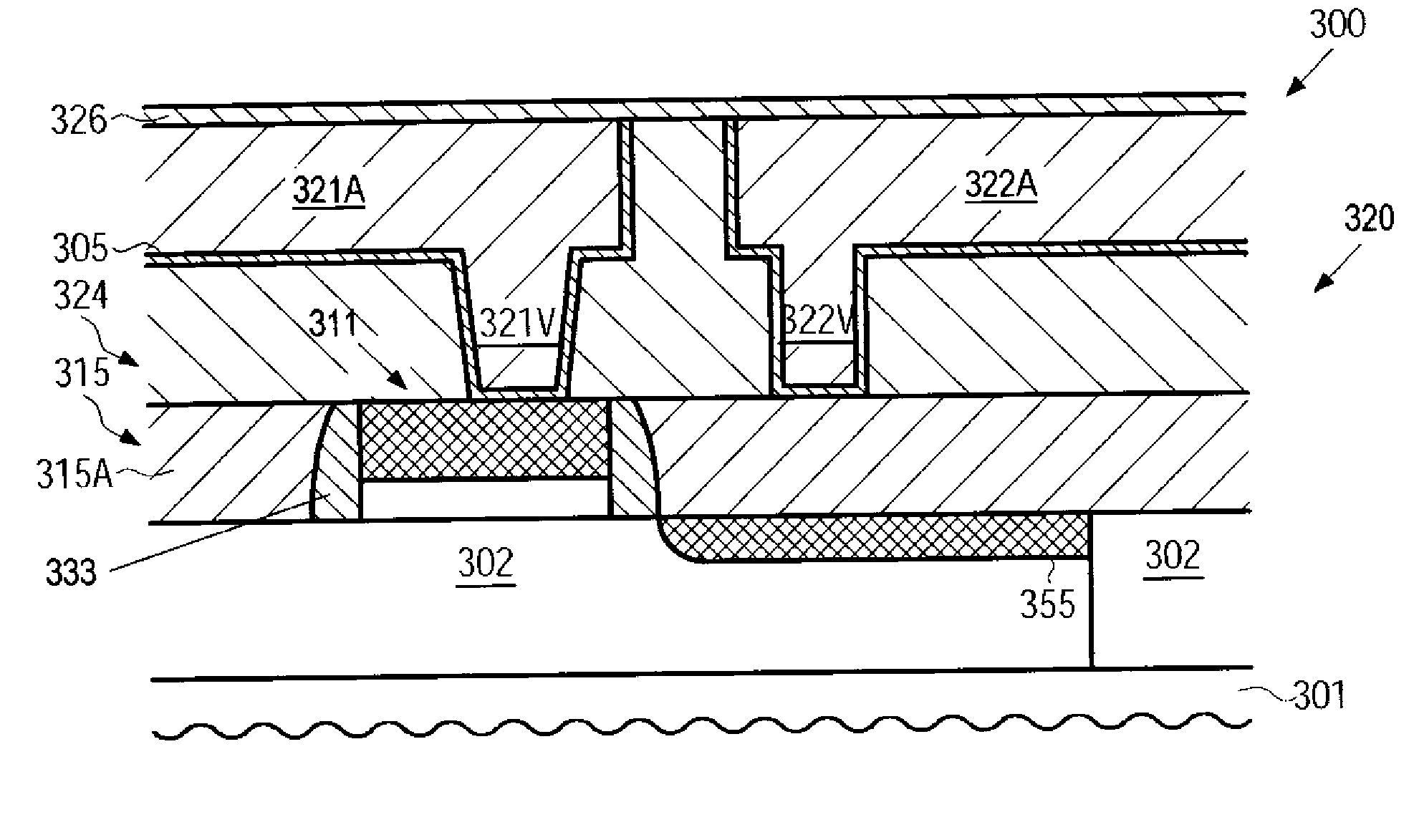
[0015]Generally, the subject matter disclosed herein relates to methods and semiconductor devices formed by these methods, wherein an enhanced contact structure may be provided in which a reduced aspect ratio of the corresponding contact openings may significantly relax any constraints posed on the respective manufacturing sequence. This is accomplished by providing the very first metallization layer as a dual damascene structure in which respective copper-based vias may connect to contact elements formed in a dielectric material having a significantly reduced thickness compared to conventional interlayer dielectric materials. Thus, the contact elements may be formed with increased process robustness due to the reduced aspect ratio, while the copper-based vias provide enhanced electrical and thermal performance. Furthermore, the dielectric material of the first metallization layer may be provided in the form of a low-k dielectric material having a permittivity of 3.0 and less, thereby enabling the reduction of the distance between the gate electrode structures and metal lines of the first metallization layer or reducing the parasitic capacitance for a similar distance compared to conventional devices.

Problems solved by technology

Due to the large number of circuit elements and the required complex layout of modern integrated circuits, the electrical connections of the individual circuit elements may generally not be established within the same level on which the circuit elements are manufactured, but require one or more additional “wiring” layers, which are also referred to as metallization layers.
Despite these advantages, copper also exhibits a number of disadvantages regarding the processing and handling of copper in a semiconductor facility.
For instance, copper readily diffuses in a plurality of well-established dielectric materials, such as silicon dioxide, wherein even minute amounts of copper, accumulating at sensitive device regions, such as contact regions of transistor elements, may lead to a failure of the respective device.
For this reason, great efforts have to be made to reduce or avoid any copper contamination during the fabrication of the transistor elements, thereby rendering copper a less attractive candidate for the formation of contact plugs, which are in direct contact with respective contact regions of the circuit elements.
Consequently, the resistance of the respective contact plugs may significantly restrict the overall operating speed of highly advanced integrated circuits, even though a highly conductive material, such as copper or copper alloys, may be used in the metallization layers.
On the other hand, any non-uniformities during the complex patterning process may result in a contact failure, which may represent one of the dominant factors that contribute to the overall yield loss.
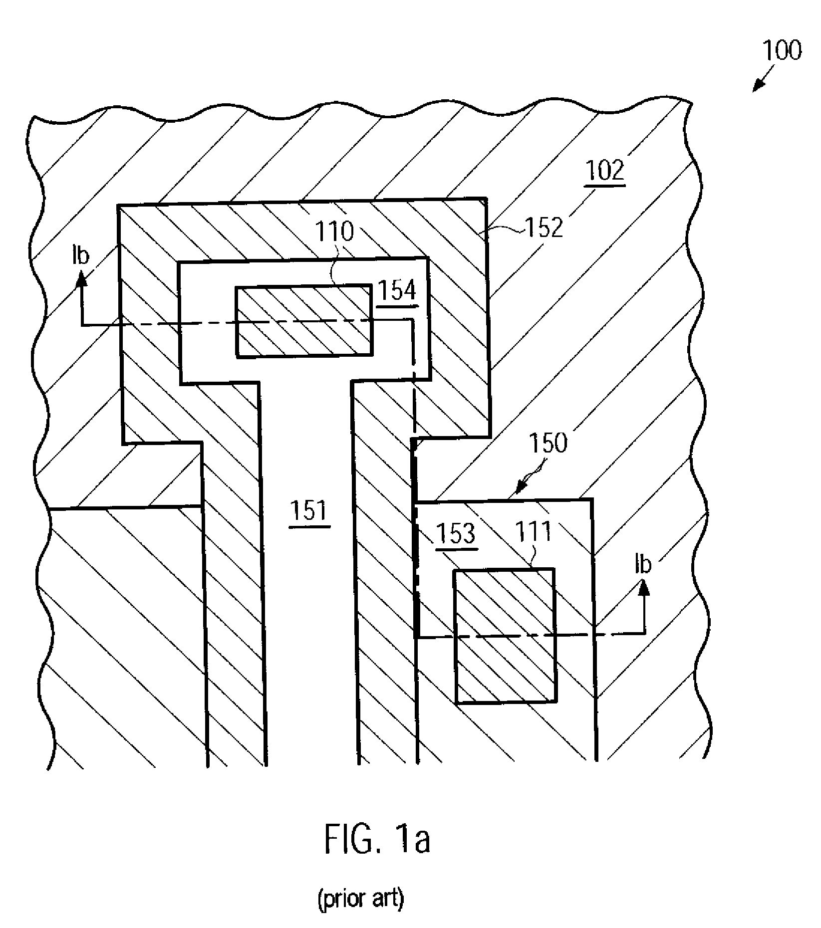
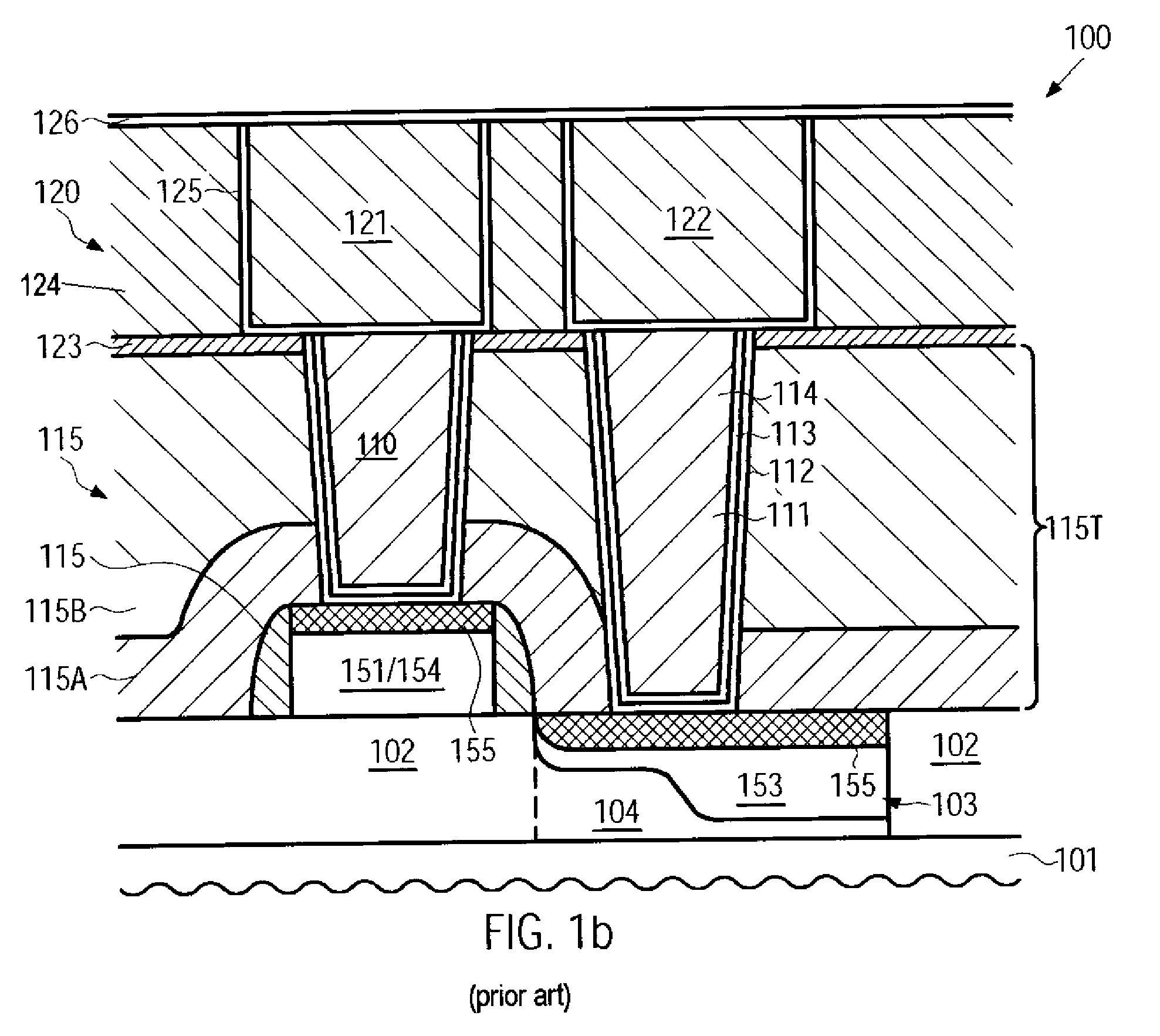
Consequently, the contact structure of the semiconductor device 100 comprises high aspect ratio contacts, such as the contact element 111, resulting in a complex patterning and deposition regime, thereby increasing the probability for reduced production yield, while also contributing to increased resistance and thus reduced electrical performance.

Method used


Image

  • Hybrid contact structure with low aspect ratio contacts in a semiconductor device
  • Hybrid contact structure with low aspect ratio contacts in a semiconductor device
  • Hybrid contact structure with low aspect ratio contacts in a semiconductor device

Examples


Embodiment Construction

[0026]Various illustrative embodiments of the invention are described below. In the interest of clarity, not all features of an actual implementation are described in this specification. It will of course be appreciated that in the development of any such actual embodiment, numerous implementation-specific decisions must be made to achieve the developers' specific goals, such as compliance with system-related and business-related constraints, which will vary from one implementation to another. Moreover, it will be appreciated that such a development effort might be complex and time-consuming, but would nevertheless be a routine undertaking for those of ordinary skill in the art having the benefit of this disclosure.

[0027]The present subject matter will now be described with reference to the attached figures. Various structures, systems and devices are schematically depicted in the drawings for purposes of explanation only and so as to not obscure the present disclosure with details ...


PUM


Abstract

By forming the first metallization layer of a semiconductor device as a dual damascene structure, the contact elements may be formed on the basis of a significantly reduced aspect ratio, thereby enhancing process robustness and also improving electrical performance of the contact structure.

Description

BACKGROUND OF THE INVENTION[0001]1. Field of the Invention[0002]The present disclosure generally relates to the field of semiconductor manufacturing, and, more particularly, to the formation of an interconnect structure directly contacting a circuit element with the first metallization level.[0003]2. Description of the Related Art[0004]Semiconductor devices, such as advanced integrated circuits, typically contain a great number of circuit elements, such as transistors, capacitors, resistors and the like, which are usually formed in a substantially planar configuration on an appropriate substrate having formed thereon a crystalline semiconductor layer. Due to the large number of circuit elements and the required complex layout of modern integrated circuits, the electrical connections of the individual circuit elements may generally not be established within the same level on which the circuit elements are manufactured, but require one or more additional “wiring” layers, which are als...

Claims


Application Information

Patent Timeline
Patent Type & Authority Applications(United States)
IPC IPC(8): H01L23/48H01L21/4763
CPCH01L21/76807H01L21/76816H01L23/485H01L23/53238H01L23/53266H01L29/665H01L2924/0002H01L29/66507H01L29/7843H01L2924/00
Inventor FEUSTEL, FRANKFROHBERG, KAIWERNER, THOMAS
Owner INNOVATIVE FOUNDRY TECH LLC
Learn More