Digital counter used for recording big figure

A counter and digital technology, applied in the field of counters, can solve the problems of counting result errors, small counting values ​​of digital counters, affecting application system performance, etc., and achieve the effect of stability

Inactive Publication Date: 2004-06-16
上海叶鑫贸易有限公司
View PDF0 Cites 2 Cited by
  • Summary
  • Abstract
  • Description
  • Claims
  • Application Information

AI Technical Summary

Problems solved by technology

[0002] In the prior art, the counting value of the digital counter is mostly not large, and some can achieve a large counting value by using an integrated chip or a programmable logic gate array. However, when a single

Method used


Image

  • Digital counter used for recording big figure
  • Digital counter used for recording big figure

Examples


Embodiment Construction

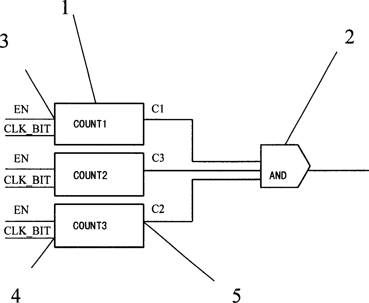
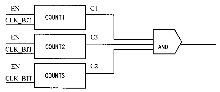
[0006] Such as figure 1 As shown, a digital counter for recording large numbers in the present invention is composed of at least two counters 1, and it is characterized in that the input end of each counter 1 is provided with an enable input port 3, and each of the counters The input end of 1 is provided with clock input port 4, and the output end of each counter 1 is provided with carry output port 5, and the carry output port 5 of each counter 1 described is connected in parallel, and is connected with an AND gate circuit 2 , the counting values ​​of each of the counters 1 are mutually prime numbers, specifically, the clock input ports 4 of each of the counters 1 are connected in parallel, and the enabling input ports 3 of each of the counting and 1 are connected in parallel, and each The counters 1 work at the same time. When the carry output port 5 of each counter 1 has a signal generated, the output signal of the AND gate circuit 2 is the product of the counts of each cou...


PUM


Abstract

The invention is a digital counter used to record great number, composed of at least two counters. Its character: input end of each counter is set with enable inlet and clock inlet, and output end set with carry outlet, all the carry outlets are connected in parallel and connected with an aND circuit, all the count values are prime, when each carry outlet generates signal, the output signal of the AND circuit is the product of numbers of all the counters.

Description

Technical field: [0001] The invention relates to a counter, in particular to a digital counter for recording large numbers. Background technique: [0002] In the prior art, the counting value of the digital counter is mostly not large, and some can achieve a large counting value by using an integrated chip or a programmable logic gate array. However, when a single counter records a large value, it will be due to External interference signals or unstable factors of the clock cause errors in the counting results, which in turn affects the performance of the entire application system. Invention content: [0003] The technical problem to be solved by the present invention is: in the prior art, the counting value of the digital counter is mostly not big, what have adopts integrated chip or programmable logic gate array to be able to reach bigger counting value, but, because single counter carries out When counting a large value, the counting result will have errors due to exte...

Claims


Application Information

Patent Timeline
IPC IPC(8): G06M3/08
Inventor 梅玲
Owner 上海叶鑫贸易有限公司
Why Eureka
Try Eureka