Rotary compressor

A rotary compressor and compressor technology, applied in the field of sealing structure, can solve the problems of reduced sealing, cost increase, refrigerant leakage, etc., and achieve the effect of improving sealing and good workability

Inactive Publication Date: 2004-06-30
DAIKIN IND LTD
View PDF2 Cites 7 Cited by
  • Summary
  • Abstract
  • Description
  • Claims
  • Application Information

AI Technical Summary

Problems solved by technology

However, in the structure using heat fitting, although sufficient airtightness can be obtained, there are problems in work when assembling the finished product
[0009] In this regard, a fixed structure in which only the frame is pressed into the casing has also been considered. However, although this situation can improve

Method used


Image

  • Rotary compressor
  • Rotary compressor
  • Rotary compressor

Examples


Embodiment approach 1

[0073] Hereinafter, Embodiment 1 of the present invention will be described in detail with reference to the drawings.

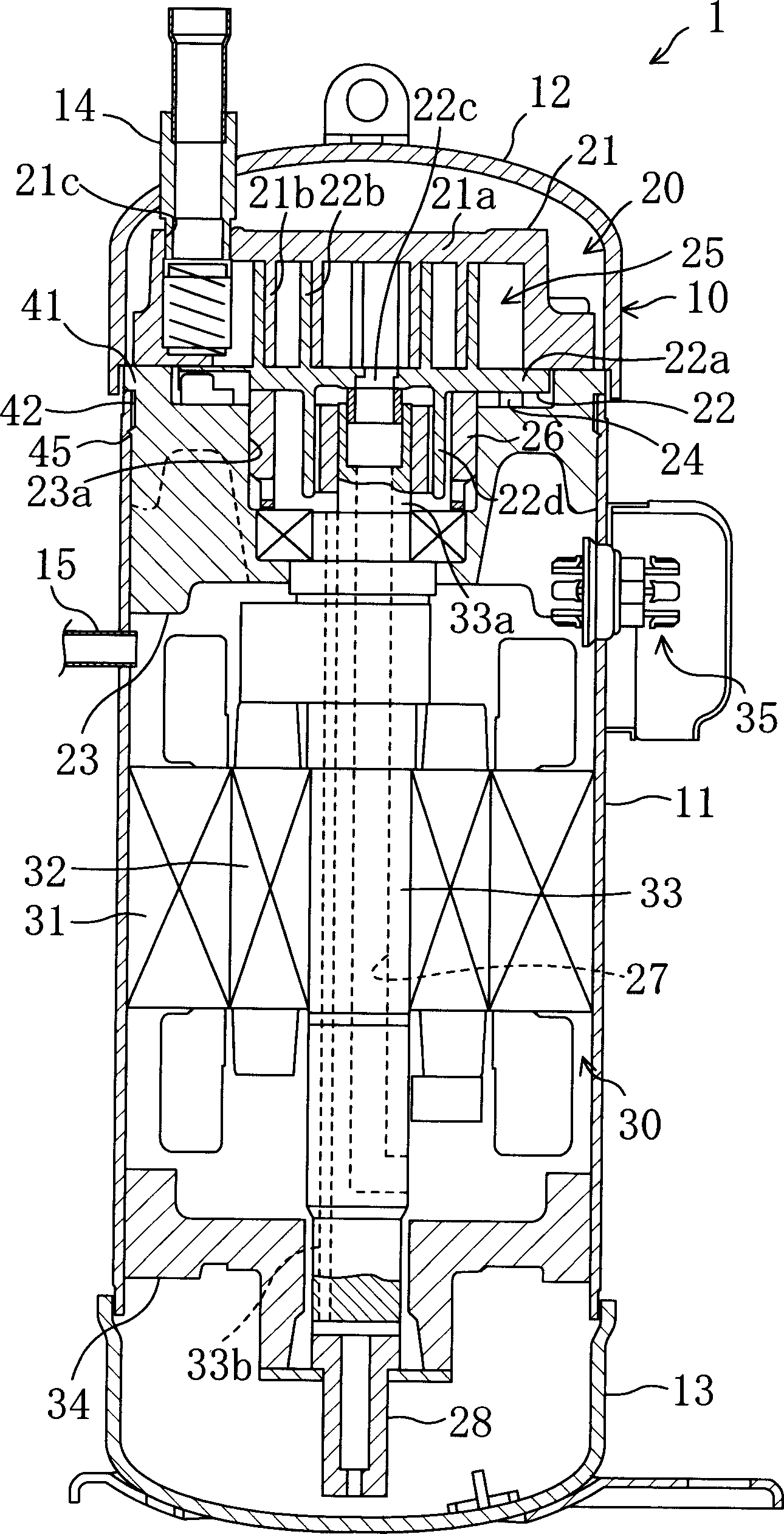
[0074] This embodiment relates to a scroll compressor. First, for the overall structure of the scroll compressor, refer to figure 1 To illustrate.

[0075] This scroll compressor (1) is used, for example, in a refrigerant circuit of a vapor compression refrigeration cycle in an air conditioner, etc., to compress a low-pressure refrigerant sucked in from the evaporator side and discharge it to the condenser side. Location. The scroll compressor (1), such as figure 1 As shown, a compression mechanism (20) and a compressor motor (30) that drives the drive mechanism of the compression mechanism (20) are provided inside the casing (10). Also, the compression mechanism (20) is arranged at the upper part of the housing (10), and the compressor motor (30) is arranged at a position slightly lower than the cylindrical part of the housing (10). Also, a connector ...

Deformed example 1

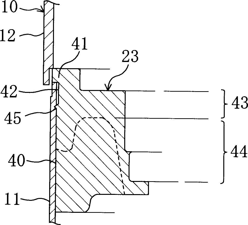
[0101] The casing (10) is formed by fitting the end cover (12) in a state where the cylindrical part (11) and the outer periphery of the frame (23) are fitted with a gap, but as Figure 4 As shown, the configuration that the end cover (12) is fitted on the inner peripheral side of the casing (10) cylinder part (11) can also be configured as an end cover ( 12) Those that can shrink due to welding. That is, as long as the circumferential groove (42) of the frame (23) is used to make the shell (10) shrink at the welding part of the cylinder part (11) and the end cover (12), the frame is strongly restricted The formation of (23) then accepts with either side of cylinder part (11) or end cap (12). In this way, the same effect as that of the first embodiment described above can also be obtained.

Deformed example 2

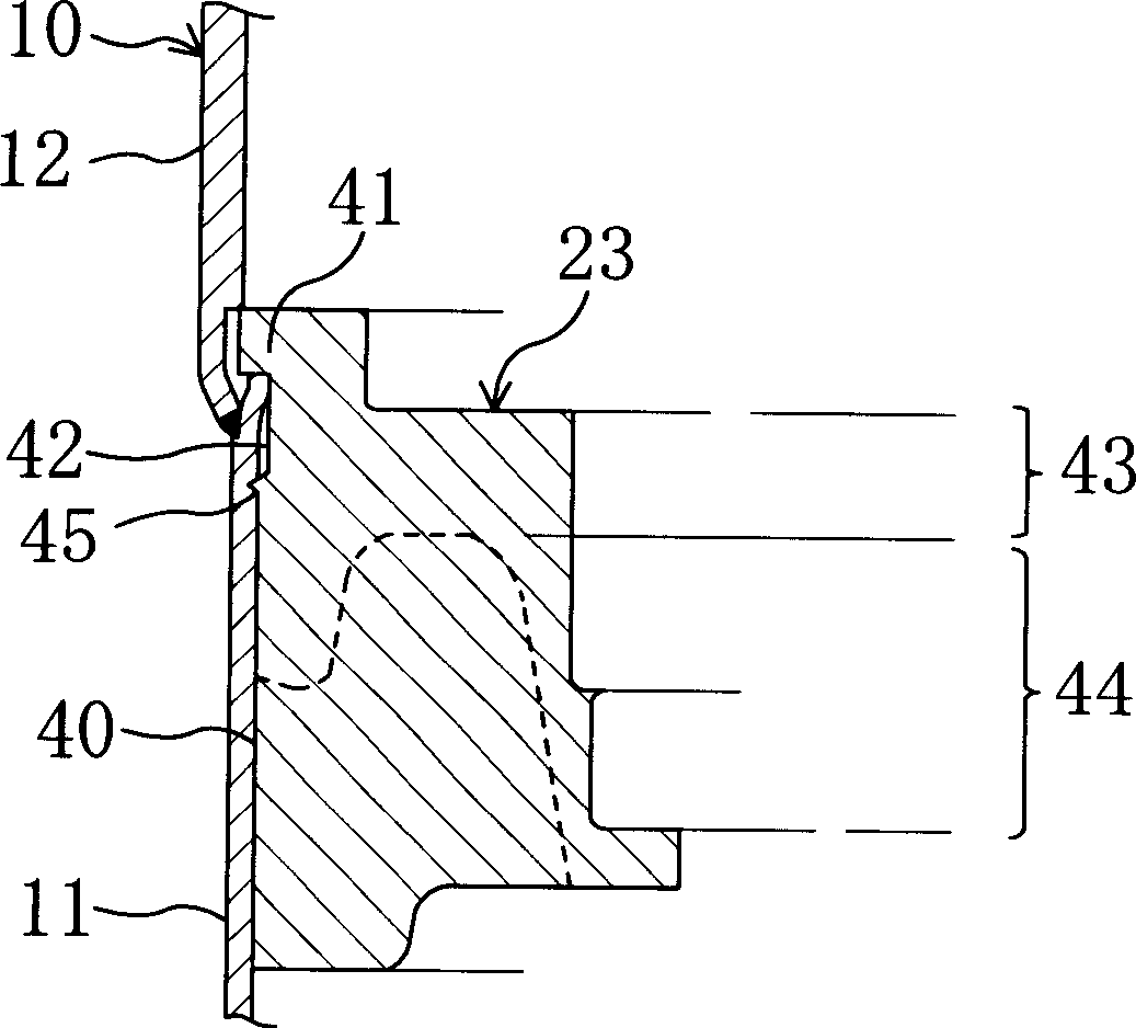
[0103] Modification 2 is a modification of the protruding portion.

[0104] Such as Figure 5 The example is that only the lower side end part (45a) of the protrusion part (45) that will be pressed into the cylindrical body part (11) is made into a tapered form, and the upper side end part is formed from the frame (23 ) is in the shape of standing at right angles to the peripheral surface (40). another example Figure 6 As an example, the upper side end portion (45b) of the protrusion portion (45) in the above-mentioned Embodiment 1 becomes a tapered surface form directly connected with the circumferential groove (42), and the end portion (45b) is made only An example of the tapered surface of the portion from the outer peripheral end of the protruding portion (45) to the outer peripheral surface (40) of the frame (23). In addition, another example Figure 7 For example, the end portions (45a), (45b) on the upper and lower sides of the protrusion (45) are not tapered, but ...


PUM


Abstract

In a rotating compressor, an outer peripheral surface (40) of a partition member (23) which is secured firmly to a casing (10) so as to divide the inside of the casing (10) into a high-level pressure space and a low-level pressure space, is provided with a peripheral groove (42) for allowing for shrinkage of the casing (10) at a weld area where a trunk part (11) and end plate (12) of the casing (10) are welded together. As a result of such arrangement, the partition member (23) is strongly tightened by making utilization of such shrinkage, thereby not only enhancing sealability between the high-level pressure space and the low-level pressure space in the inside of the casing (10) but also preventing a drop in workability during assembling and an increase in cost.

Description

technical field [0001] The present invention relates to a rotary compressor, in particular to a seal structure between a high-pressure space and a low-pressure space in a casing. Background technique [0002] In the past, rotary compressors including scroll type (scroll), swing type (swing), or rolling piston type (rollingpiston) (rotary-rotary) and other compression mechanisms, for example, in (Japan) The method disclosed in KOKAI Publication No. 2000-97183 can be used for compressing refrigerant gas in a refrigerating device that performs a refrigerating cycle in an air conditioner or the like. A compressor motor is incorporated in a rotary compressor, and the compressor motor is used as a power source to drive the compression mechanisms of the above-mentioned various systems. [0003] Here, with regard to the schematic structure of conventional rotary compressors, Figure 10 A scroll-type compressor (100) is shown for illustration. [0004] The...

Claims


Application Information

Patent Timeline
IPC IPC(8): F04B39/12F01C21/10F04C18/02F04C23/00F04C27/00
CPCF04C2230/60F04C23/008F04C2240/30F04C2230/231F04C18/0215F01C21/10F04C29/00
Inventor 松川和彦柳泽雅典北浦洋
Owner DAIKIN IND LTD
Why Eureka
Try Eureka