Louvered fins for heat exchanger

A heat exchanger and fin technology, applied in heat exchange equipment, indirect heat exchangers, heat exchanger types, etc., can solve problems such as insufficient heat exchange performance level and difficulty in adapting to belt thickness.

Inactive Publication Date: 2004-06-30
LAIR LIQUIDE SA POUR LETUDE & LEXPLOITATION DES PROCEDES GEORGES CLAUDE +1
View PDF0 Cites 18 Cited by
  • Summary
  • Abstract
  • Description
  • Claims
  • Application Information

AI Technical Summary

Problems solved by technology

This cut is insufficient to achieve the level of heat exchange performance required in industrial exchangers
[0025] Third, the traditional method of manufacturing louvered corrugations, i.e., the manufacturing metho...

Method used


Image

  • Louvered fins for heat exchanger
  • Louvered fins for heat exchanger
  • Louvered fins for heat exchanger

Examples


Embodiment Construction

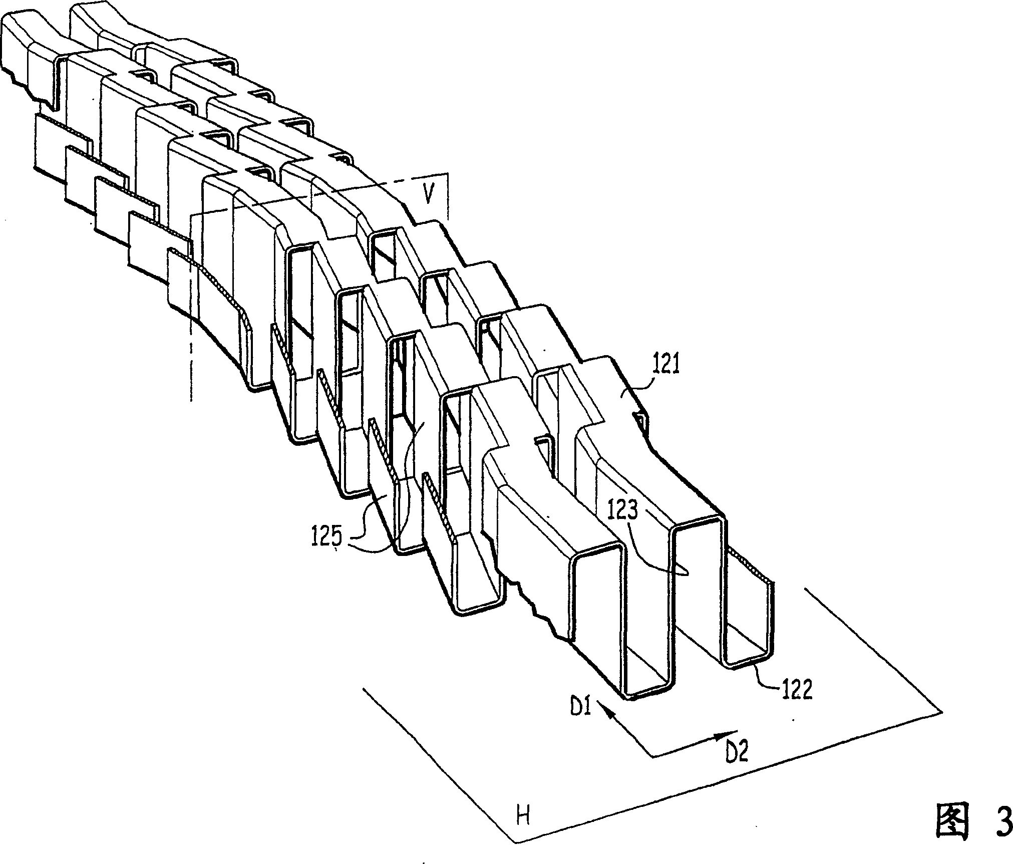
[0068] Figure 3 depicts a louvered corrugation according to the invention having a general main direction D1 of the corrugation and a cross-section in the form of a square wave ( Figure 4 ), the square wave thus defined extends along a direction D2 perpendicular to the direction D1. Here, for convenience of description, these two directions are also assumed to be horizontal directions.

[0069] The term "square wave" here means a succession, alternation of horizontal and vertical segments, the horizontal segments being aligned with each other.

[0070] The ribs have corrugated tops 121 defined by square wave crests, which are flat and horizontal. The ribs also have corrugated recesses 122 defined by square wave troughs, which are also flat and horizontal. Tops 121 and recesses 122 alternately connect corrugated flanks 123, which are vertical and flat, the mean planes of which extend perpendicular to direction D2.

[0071] Cut from the corrugated flanks 123 are a series of ...


PUM

PropertyMeasurementUnit
Wall thicknessaaaaaaaaaa

Abstract

The fin comprises a set of undulating legs (23) connected alternately by an undulating top and by an undulating base. The legs are provided with flaps (25) cut in the legs and inclined at an angle (alpha ) relative to the principal undulating direction (D1). The legs have a thickness (e), an average transverse spacing (w) which define the width of the passage channel and the flaps have a length (ls) greater than the pitch (p). An independent claim is included for a heat exchanger utilizing the fins.

Description

technical field [0001] The present invention relates to a corrugated fin / fin for a plate-fin heat exchanger. Background technique [0002] There are various types of plate-to-plate heat exchangers, each suitable for one field of application. In particular, the invention is advantageously used for the separation of air or H by cryogenic distillation 2 / CO (hydrogen / carbon monoxide) mixture heat exchanger equipment. [0003] The heat exchanger can be a main heat exchange circuit or a reboiler / condenser. [0004] Fig. 1 is a partially cutaway perspective view showing an example of such a conventionally structured heat exchanger to which the present invention is to be applied. [0005] Said heat exchanger 1 consists of a set of parallel rectangular plates 2, identical, defining between them passages for fluids placed in indirect heat exchange relation. In the example described, these channels are successive and cyclic channel 3 for the first fluid, channel 4 for the second f...

Claims


Application Information

Patent Timeline
IPC IPC(8): F28F1/30B01J19/24B01J19/32B21D53/04F25J3/00F25J5/00F28D9/00F28D9/02F28F3/02
CPCB01J19/32F25J5/002F25J2290/42F25J2210/18B01J19/249B01J2219/32213F28F3/027B01J2219/3221F28D9/0068F25J2290/10B01J2219/32248B01J2219/32475B21D53/04F25J2210/40B01J2219/32241B01J2219/328F25J3/04F28F2250/108
Inventor D·阿弗鲁M·格里韦尔M·瓦格纳F·查特尔-佩拉热F·芬特斯C·蒂尔吉E·韦尔伦
Owner LAIR LIQUIDE SA POUR LETUDE & LEXPLOITATION DES PROCEDES GEORGES CLAUDE
Why Eureka
Try Eureka