Supporting structure of transverse engine

A supporting structure and engine technology, applied in the direction of engine base, supporting machine, mechanical equipment, etc., can solve problems such as durability defects of hydraulic support parts, achieve the effect of improving the degree of freedom of arrangement, increasing the degree of freedom of arrangement, and eliminating longitudinal movement

Inactive Publication Date: 2004-07-07
HONDA MOTOR CO LTD +1
View PDF2 Cites 17 Cited by
  • Summary
  • Abstract
  • Description
  • Claims
  • Application Information

AI Technical Summary

Problems solved by technology

Therefore, the hydraulic bearing described in Japanese Patent Laid-Open No. Sho 63-61533 is defective in durability

Method used


Image

  • Supporting structure of transverse engine
  • Supporting structure of transverse engine
  • Supporting structure of transverse engine

Examples


Embodiment Construction

[0060] First of all, since the present invention is under the assumption of a transverse engine, the transverse engine will be described first, followed by the detailed structure of the hydraulic support, and then an exemplary hydraulic support preferably used for the transverse engine. The layout is explained.

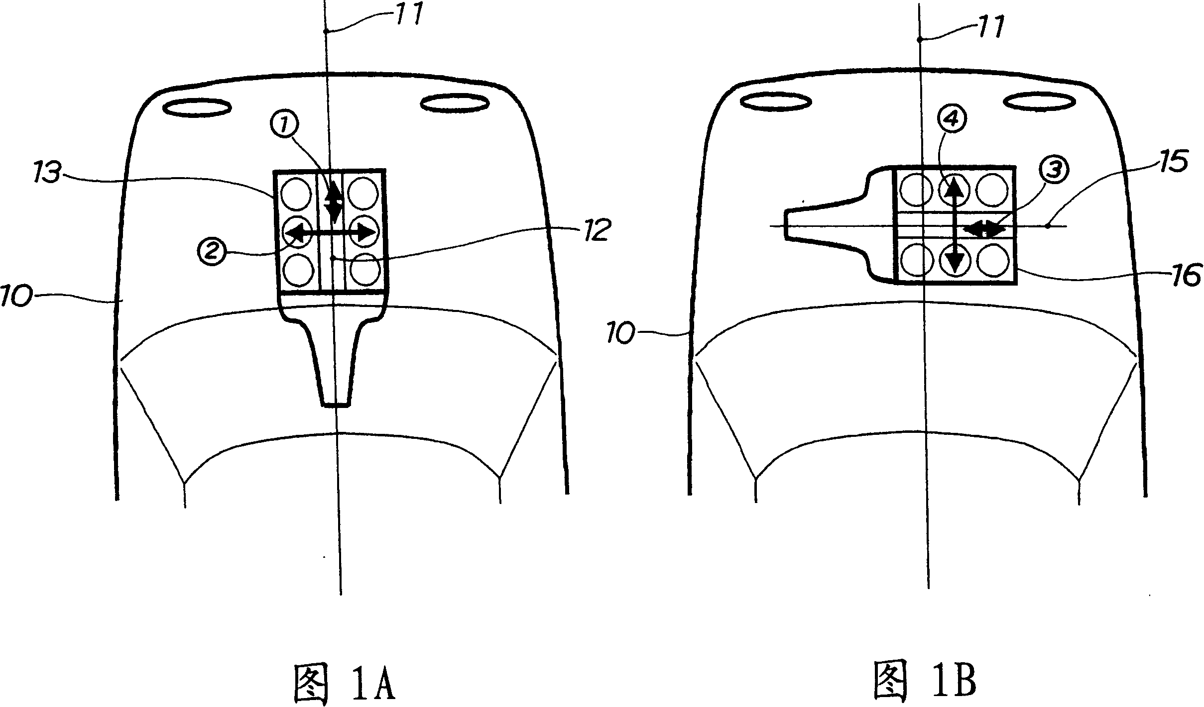
[0061] Reference is now made to FIGS. 1A and 1B , which schematically illustrate a vehicle 10 with a longitudinal engine and a transverse engine, respectively, for comparison.

[0062] An engine arranged with a crankshaft 12 arranged parallel to the longitudinal axis 11 of the vehicle is referred to as a longitudinal engine 13 . Due to the characteristics of the reciprocating engine, the vibration along the crankshaft 12 becomes small as indicated by arrow ①, and the vibration along the direction perpendicular to the crankshaft 12 becomes large as indicated by arrow ②.

[0063] That is, in the longitudinal engine 13, even if the spring constant of the engine mount al...


PUM


Abstract

A structure for supporting, via an engine mount, a transversal engine having a crankshaft (15) laid horizontally at a right angle to a vehicle longitudinal axis (11), on a vehicle body, is disclosed. The engine mount includes at least one inclined hydro mount (20) in which a working fluid (33) is enclosed and a maximum damping generating axis (30) is inclined a predetermined angle with respect to a vertical line. The inclined hydro mount is disposed inwardly of a total width in a power plant (54) which includes the transversal engine and a transmission (53).

Description

technical field [0001] The invention relates to an engine mount for supporting an engine having a crankshaft arranged horizontally at right angles to the longitudinal axis of the vehicle. Background technique [0002] In general, as an engine mount for supporting a motor vehicle engine, a structure in which a liquid is sealed is known, as disclosed in, for example, Japanese Patent (Examined) Kokai No. 63-61533. [0003] The following will refer to Figure 17 with Figure 18 This conventional engine mount will be described. [0004] exist Figure 17 Among them, reference numeral 101 represents the upper base plate, reference numeral 102 represents the lower base plate, reference numeral 103 represents bolts for connecting the upper base plate 101 to the engine, reference numeral 104 represents a support body fixed on the vehicle frame, reference numerals 105 and 106 denotes a rubber elastic body, reference numeral R1 denotes an upper liquid chamber, reference numeral R2 den...

Claims


Application Information

Patent Timeline
Patent Type & Authority Applications(China)
IPC IPC(8): B60K5/12F16F13/06F16F13/10
CPCF16F13/108B60K5/1216F16F13/10B60K5/1208
Inventor 宫本康生雷纳·海斯
Owner HONDA MOTOR CO LTD
Why Eureka
Try Eureka