Wiring equipment
An appliance and wiring technology, applied in the field of wiring appliances, can solve the problems that the design of the remote control and the wiring appliance has its limits and troubles.
- Summary
- Abstract
- Description
- Claims
- Application Information
AI Technical Summary
Problems solved by technology
Method used
Image

Examples
no. 1 approach
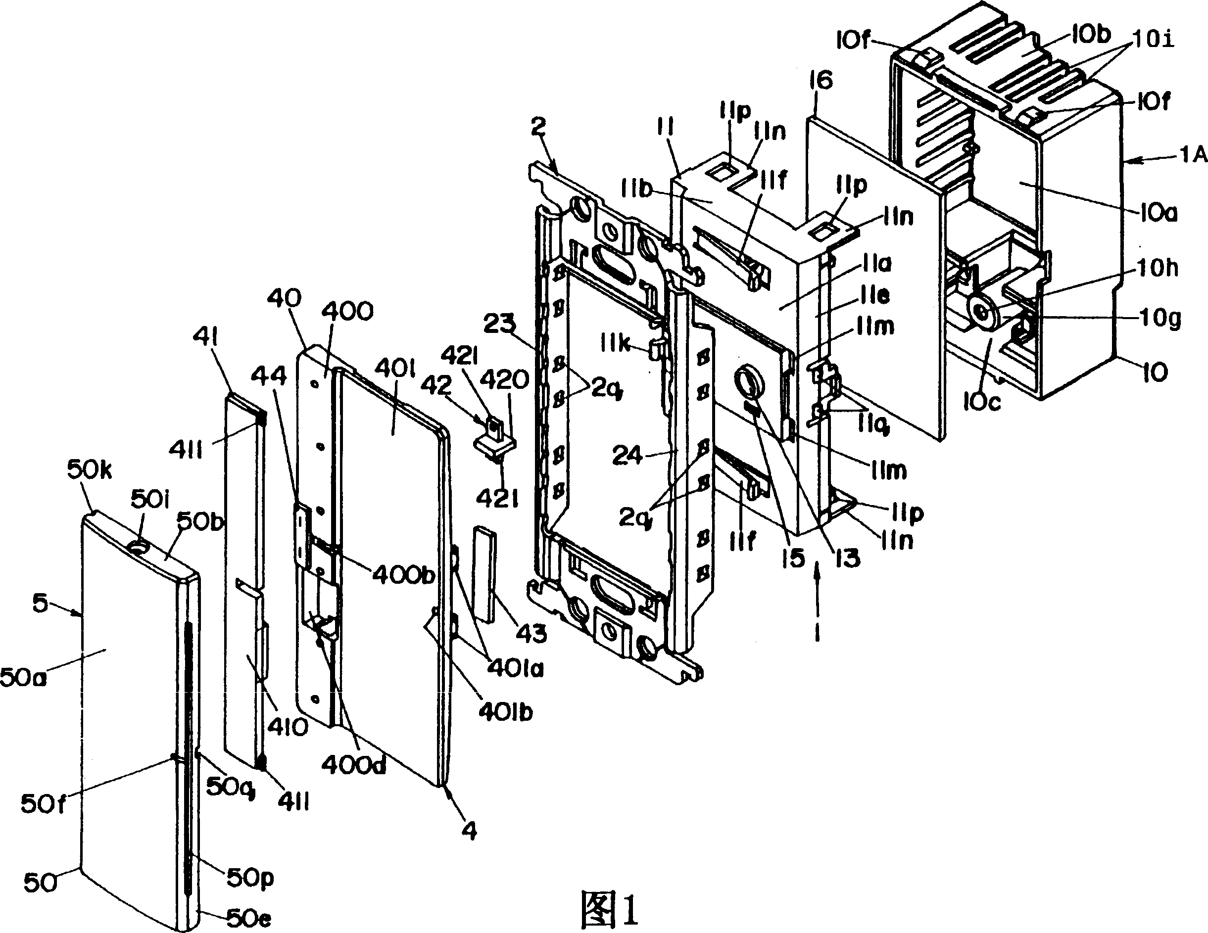
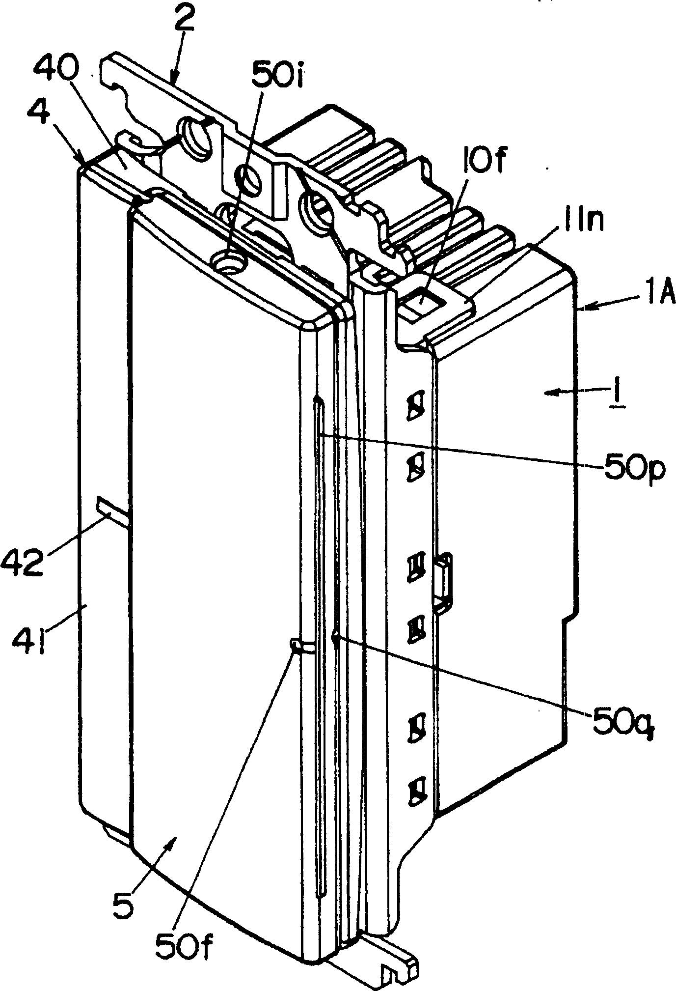
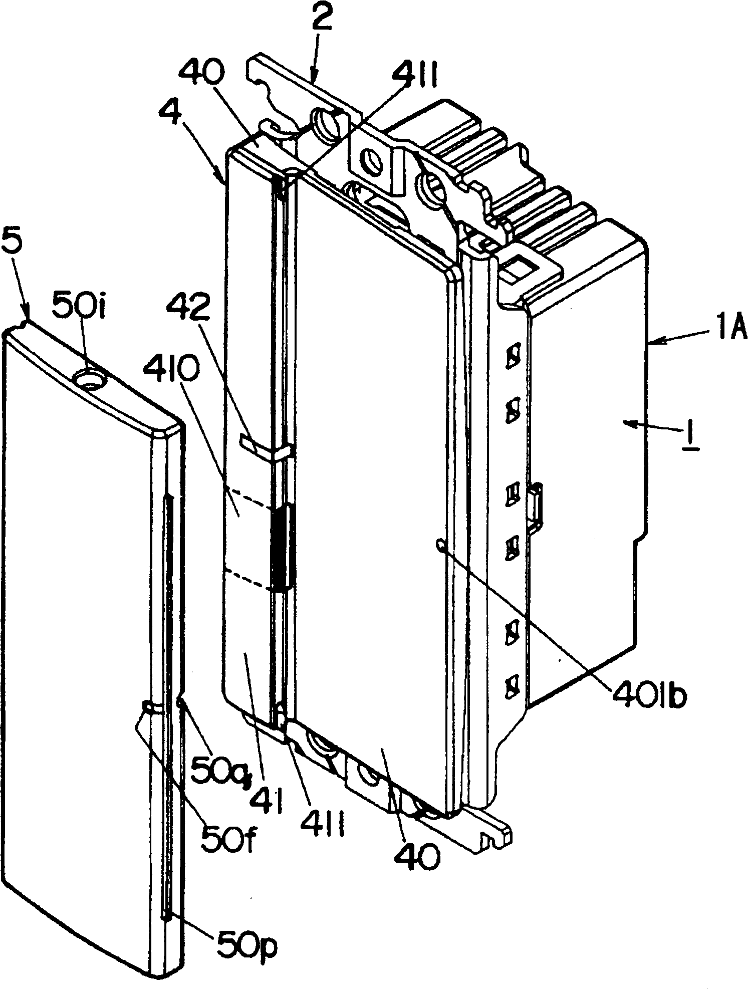
[0043]Fig. 1 is an exploded perspective view of a wiring appliance according to a first embodiment of the present invention, figure 2 It is a perspective view of the wiring appliance, image 3 It is a perspective view of the same wiring appliance with the remote controller separated from the main body of the wiring appliance, Figure 4 It is a perspective view when the wiring appliance body of the same wiring appliance is installed in the fixed frame, and Fig. 5 is a circuit diagram of the same wiring appliance, Image 6 It is the rear view of the handle of the wiring appliance.
[0044] The wiring appliance of the first embodiment is characterized in that, as shown in Fig. 1 to Figure 4 , equipped with: a wiring appliance body 1, a fixed frame 2, a frame-shaped plate composed of a connecting frame and a decorative plate for the plate (refer to the following description) Figure 15 ), a handle 4, and a remote controller 5; the wiring appliance body 1 possesses, and is embe...
no. 2 approach
[0095] Fig. 8 is a wiring appliance according to the second embodiment of the present invention, a perspective view (a) after the remote controller is removed and a back view (b) of the remote controller, Fig. 9 is an exploded perspective view of the wiring appliance body of the same wiring appliance, and Fig. 10 is Front view (a), top view (b) and right view (c) of the cover of the same wiring appliance body.
[0096] As shown in Fig. 8 and Fig. 9, the wiring appliance of the second embodiment is characterized in that it is equipped with a wiring appliance body 1, a decorative plate 32, a handle 4 and a remote controller 5, etc., and the difference from the first embodiment is that the set size is It can be installed in the embedding box and 86 boards specified in GB 1245. The remote controller 5 has a timer function (mechanism). Using this timer function, from the predetermined timing start time such as when operating, through the predetermined time corresponding to the opera...
no. 3 approach
[0127] Figure 15 It is the wiring appliance which concerns on the 3rd embodiment of this invention, and the perspective view which removed the remote control from the wiring appliance main body side.
[0128] As shown in Figure 1, the wiring appliance of the third embodiment is composed of a wiring appliance body 1, a fixed frame not shown in the figure, a frame-shaped plate 3 composed of a connecting frame 31 and a decorative plate 32 for a plate, and a remote controller 5, and complies with JIS C The classification of 8304 sets the size for wide handle-shaped special switches such as small switches for indoor use.
[0129] Among the above-mentioned wiring device body 1, fixed frame, plate 3 and remote controller 5, the fixed frame and plate 3 are the same as existing ones, and the wiring device body 1 and remote controller 5 will be described in detail below.
[0130] The wiring appliance body 1 is embedded in the wall for use, and is equipped with a housing 1A composed of...
PUM
 Abstract
Description
Claims
Application Information