
Lateral transistor

A technology of lateral transistors and emitter regions, which is applied in the direction of transistors, semiconductor devices, semiconductor/solid-state device manufacturing, etc., and can solve the problem of increasing the current amplification factor in time sequence

Inactive Publication Date: 2004-08-04
RENESAS TECH CORP
View PDF1 Cites 2 Cited by
  • Summary
  • Abstract
  • Description
  • Claims
  • Application Information

AI Technical Summary

Problems solved by technology

[0006] However, in conventional lateral transistors, there is a problem that the current amplification factor increases in chronological order

Method used


Image

  • Lateral transistor
  • Lateral transistor
  • Lateral transistor

Examples


Embodiment

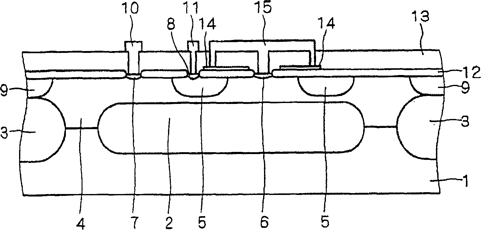
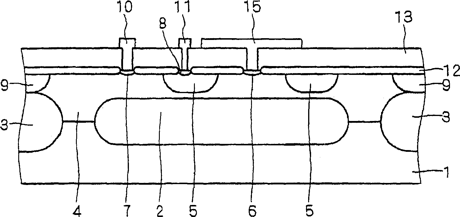
[0018] figure 1 is a cross-sectional view showing the structure of the lateral transistor of this embodiment.

[0019] exist figure 1 In this method, an N+ type buried diffusion layer 2 and a P+ type isolation diffusion layer 3 are formed at predetermined positions within the surface of a P − type semiconductor substrate 1 . In addition, a base region 4 made of an N-type epitaxial layer is formed to cover the P-type semiconductor substrate 1 , the N+ type buried diffusion layer 2 and the P+ type isolation diffusion layer 3 .

[0020] Here, on the upper part of the P+ type isolation diffusion layer 3, a P type isolation diffusion layer 9 is formed, and the P+ type isolation diffusion layer 3 and the P type isolation diffusion layer 9 form an isolation region.

[0021] In addition, an oxidation treatment of hundreds of nanometers is carried out on the surface of the base region 4. After photolithography, boron etc. are implanted, and heat treatment at a temperature higher th...


PUM


Abstract

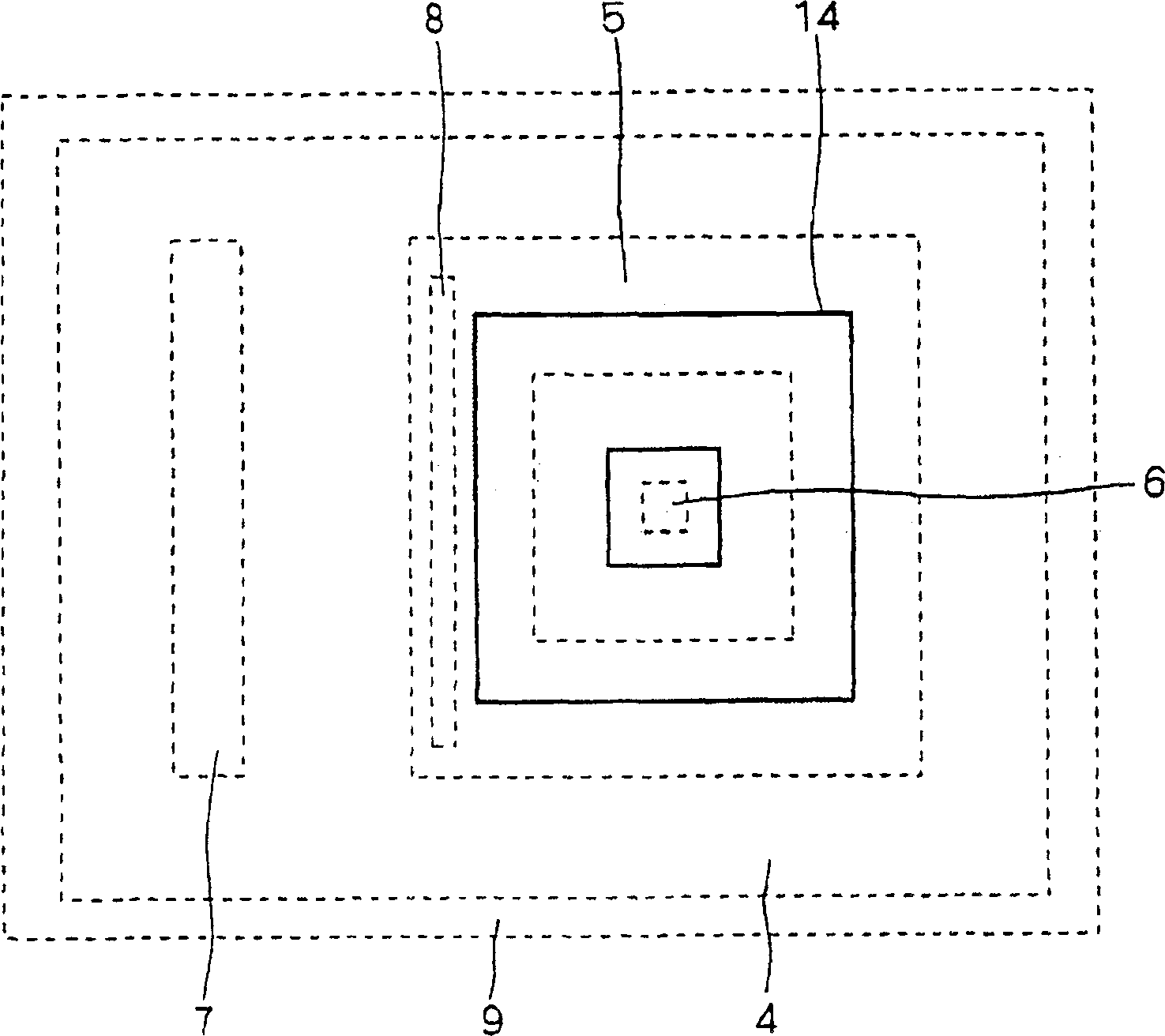
It is an object to provide a lateral transistor which enables a current gain rate to change less, even if it is used over a long time. In the lateral transistor according to the present invention, a polysilicon layer (14) is formed to cover a collector region (5) and a base region (4) on a LOCOS oxide film (a field insulating film) (12) from a collector region (5) to an emitter region (6). Furthermore, in order to connect electrically that polysilicon layer (14) and the emitter region (6) with each other, the polysilicon layer (14) and the emitter region (6) are connected with each other by a wiring (15).

Description

technical field [0001] The invention relates to a lateral transistor, in particular to a lateral transistor structure capable of maintaining a stable current amplification factor for a long time. technical background [0002] So far, lateral transistors have been used in products such as automobiles, electric motors, fluorescent displays, and audio devices. [0003] Here, the lateral transistor refers to a transistor in which the emitter, the collector, and the base are all formed on the same surface of the substrate, and the component parallel to the surface of the minority carrier flow injected from the emitter controls the operation of the transistor. (For example, refer to Patent Document 1) [0004] Patent Document 1 [0005] Japanese Patent Application Publication No. 5-36701 ( figure 2 ) [0006] However, in conventional lateral transistors, there is a problem that the current amplification factor increases sequentially over time. Contents of the invention [0...

Claims


Application Information

Patent Timeline
Patent Type & Authority Applications(China)
IPC IPC(8): H01L21/331H01L29/06H01L29/417H01L29/73H01L29/735H01L29/78
CPCH01L29/41708H01L29/735H01L29/78
Inventor 山本文寿榎原敏之
Owner RENESAS TECH CORP
Learn More