
Pulse tube refrigerator

A technology of pulse tube refrigeration and condenser, which is applied in refrigerators, refrigeration components, refrigeration and liquefaction, etc., and can solve problems such as the decrease of the current carrying capacity of superconducting coils

Inactive Publication Date: 2004-08-11
OXFORD MAGNET TECH LTD
View PDF3 Cites 3 Cited by
  • Summary
  • Abstract
  • Description
  • Claims
  • Application Information

AI Technical Summary

Problems solved by technology

If the cryocooler can absorb 1W at 4.2K (such as the model RDK408 supplied by SumitomoHeavy Industries), then the temperature of the recondenser will increase to 4.7K, which causes a drastic drop in the current carrying capacity of the superconducting coil

Method used


Image

  • Pulse tube refrigerator
  • Pulse tube refrigerator
  • Pulse tube refrigerator

Examples


Embodiment Construction

[0023] The best form contemplated by the inventors for carrying out the invention is described with reference to examples. In the following description, numerous details are set forth in order to provide a complete understanding of the present invention. However, it will be apparent to those skilled in the art that the invention may be practiced with various modifications described in the specific embodiments.

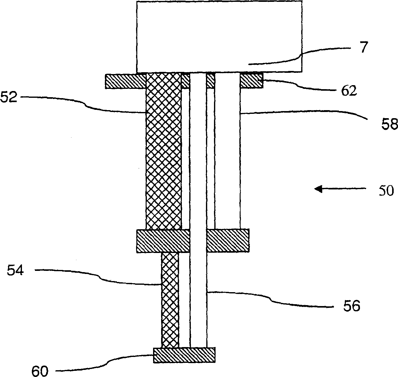
[0024] refer to Figure 6 , which shows a first embodiment of the invention in which a two-stage pulse tube refrigerator arrangement is shown. Regenerator tubes 92, 94 and impulse tubes 96, 98 are shown, with regenerator tube 94 being finned.

[0025] Figure 6A A cross-sectional view through regenerator tube 94 is shown showing annular fins 104 in the form of annular disks surrounding tube 94 . The regenerator tube walls are suitably manufactured simultaneously with the fins, preferably from the same material with moderate thermal conductivity, for example austeniti...


PUM


Abstract

The present invention relates to pulse tube refrigerators for recondensing cryogenic liquids. In particular, the present invention relates to the same for magnetic resonance imaging systems. In many cryogenic applications components, e.g. superconducting coils for magnetic resonance imaging (mri), superconducting transformers, generators, electronics, are cooled by keeping them in contact with a volume of liquified gases (e.g. helium, neon, nitrogen, argon, methane). In a first aspect, the present invention provides pulse tube refrigerator (PTR) arrangement within a cryogenic apparatus, wherein a regenerator tube of the PTR is finned. In this configuration the fins or baffles, are believed to increase the surface area available for distributed heat transfer from the helium atmosphere to the regenerator.

Description

technical field [0001] The present invention relates to a pulse tube refrigerator for recondensing cryogenic liquids. In particular, the invention relates to pulse tube refrigerators for magnetic resonance imaging systems. Background technique [0002] In many cryogenic applications, by keeping components such as superconducting coils for magnetic resonance imaging (MRI), superconducting transformers, electronic devices, and large quantities of liquefied gases (such as helium, neon, nitrogen, argon, methane) Contact to cool these parts. Any heat dissipation in these components or heat into the system will cause a portion to vaporize. In order to make up for this loss, replenishment is required. This working operation is considered problematic by users and many efforts have been made over the years to introduce refrigerators which recondense any lost liquid for return to the bath. [0003] exist figure 1 A two-stage Gifford McMahon (GM) cold head recondenser for an MRI (...

Claims


Application Information

Patent Timeline
Patent Type & Authority Applications(China)
IPC IPC(8): F28F1/16F25B9/00F25B9/14F28F1/12F28F1/24F28F1/26F28F1/32F28F1/36
CPCF25B2400/17F25B2309/1412F25B9/145F28F1/24F25B2309/1408F25B2309/1414F28F1/124F25B2309/1415F25B9/10
Inventor H·潘T·休斯K·怀特
Owner OXFORD MAGNET TECH LTD
Features
  • Generate Ideas
  • Intellectual Property
  • Life Sciences
  • Materials
  • Tech Scout
  • Unparalleled Data Quality
  • Higher Quality Content
  • 60% Fewer Hallucinations
Learn More