
Sequencing frequency divider

A frequency dividing device, the technology of input clock, applied in the direction of using record carrier and instructions for program control, data processing power supply, etc., can solve the problems of jitter, the duty cycle is not 50%-50%, etc., to achieve the effect of low operating clock

Inactive Publication Date: 2004-08-18
ELAN MICROELECTRONICS CORPORATION
View PDF0 Cites 2 Cited by
  • Summary
  • Abstract
  • Description
  • Claims
  • Application Information

AI Technical Summary

Problems solved by technology

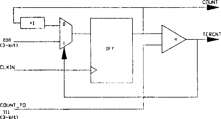
like Figure 2B As shown, if this pulse signal is used for the clock (CLOCK), there may be a shortcoming that the duty cycle is not 50%-50%, and glitch may also occur

Method used


Image

  • Sequencing frequency divider
  • Sequencing frequency divider
  • Sequencing frequency divider

Examples


Embodiment Construction

[0038] Regarding the technology, means and specific structural features adopted by the present invention to achieve the above-mentioned purpose, a preferred and feasible embodiment is now given, and further disclosed by illustrations, as follows.

[0039] The present invention provides a programmable frequency division device for converting an input clock (which can be generated by an oscillator) into a target clock, the frequency of the input clock being 2 times the frequency of the target clock m times, where m is a positive integer greater than 0, please refer to FIG. 3A , the device includes: an n-bit adder 31 and an n-bit D-type flip-flop 32 . An adjustment parameter 301 and a feedback signal 302 are input to the adder 31, and the adder 31 adds the adjustment parameter 301 and the feedback signal 302 to generate a first output signal 303, and outputs the signal 303, wherein the adjustment parameter includes n bits , n is a positive integer greater than 0, and m≤n (for exa...


PUM


Abstract

The invention provides a programmed frequency division apparatus comprising an n digit adder and an n digit type D trigger for switching an input clock into a target clock, and the input clock frequency is the m to the power of 2 times of the destination clock frequency, the adder produces a first output signal based on an adjustment parameter and a feedback signal. The type D trigger is connected with the adder to form a ring form loop for receiving a first output signal and the input clock and producing a second output signal.

Description

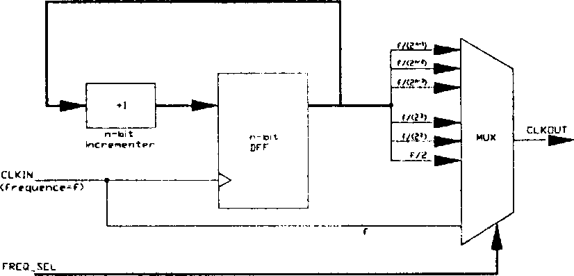
technical field [0001] The present invention relates to a frequency division device, in particular to a programmable frequency division device that can be controlled by computer program instructions. Background technique [0002] In a synchronous digital system, the clock signal plays a very important role. In addition to determining the performance of the system, it is also closely related to the power consumption of the circuit. In particular, modern mobile devices are all the rage. Many computer central processing units (CPUs), digital signal processors (DSPs), and microcontrollers are designed to reduce power consumption as much as possible to save power. Switches the system to a lower operating frequency when the processor is idle. [0003] For general traditional crossover devices, please refer to Figure 1A , is usually composed of an n-bit D-type flip-flop (DFlip Flop) and an incrementer (incrementer), and the different frequency signals obtained after frequency div...

Claims


Application Information

Patent Timeline
IPC IPC(8): G06F1/32G06F9/04
Inventor 王荣志胡肇佑
Owner ELAN MICROELECTRONICS CORPORATION
Learn More