Optical height adjusting device

A technology of height adjustment and optics, which is applied to the parts of the instrument, instruments, etc., can solve the problems of complex structure, space occupation, and time-consuming installation of the high-precision mobile platform 104

Inactive Publication Date: 2004-08-18
IND TECH RES INST
View PDF0 Cites 4 Cited by
  • Summary
  • Abstract
  • Description
  • Claims
  • Application Information

AI Technical Summary

Problems solved by technology

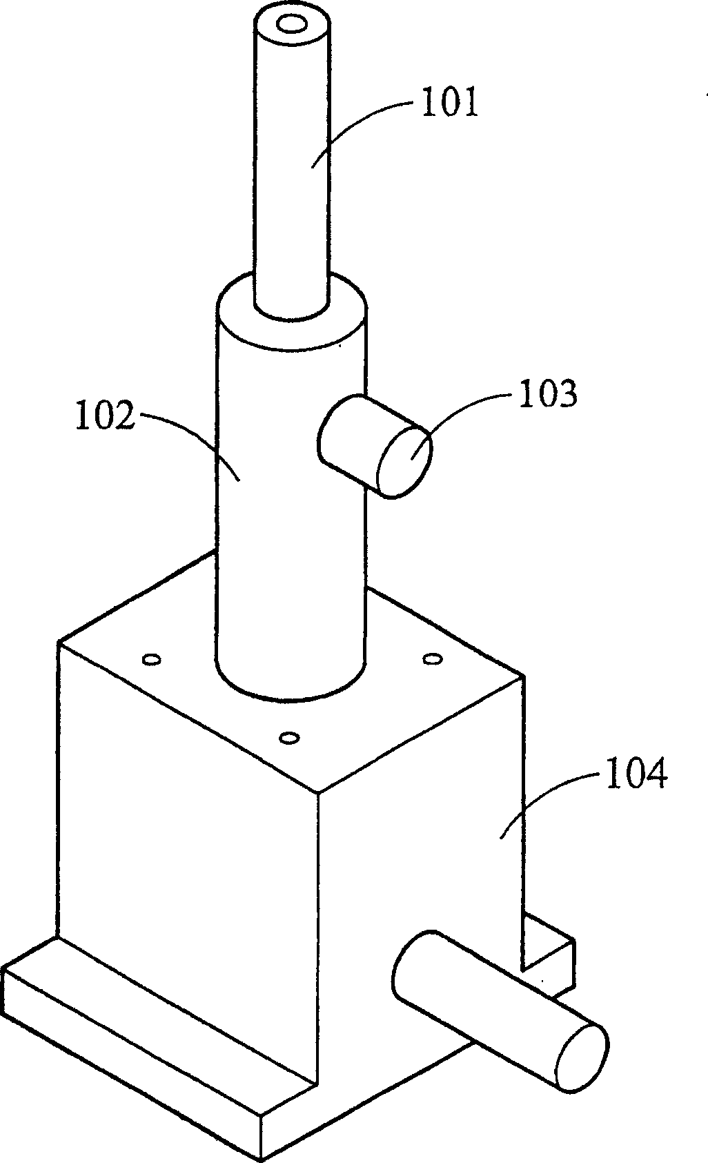
Optical components, such as lenses, etc., are installed on the support rod 101. The support rod 101 is located on the support seat 102, and the support rod 101 is moved up and down by manual stretching to perform alignment. After alignment, the rotation knob 103 is used to fix the support Rod 101, but this device can only be adjusted roughly, and it must be matched with a high-precision mobile platform 104 to meet the optical requirements for high precision. However, this high-precision mobile platform 104 is complex in structure, expensive, takes up space, and requires It is also time-consuming, and the support rod 101 is easy to loosen in addition, resulting in a reduction in work efficiency

Method used


Image

  • Optical height adjusting device
  • Optical height adjusting device
  • Optical height adjusting device

Examples


Embodiment Construction

[0030] A preferred embodiment of the present invention will now be described with reference to the accompanying drawings.

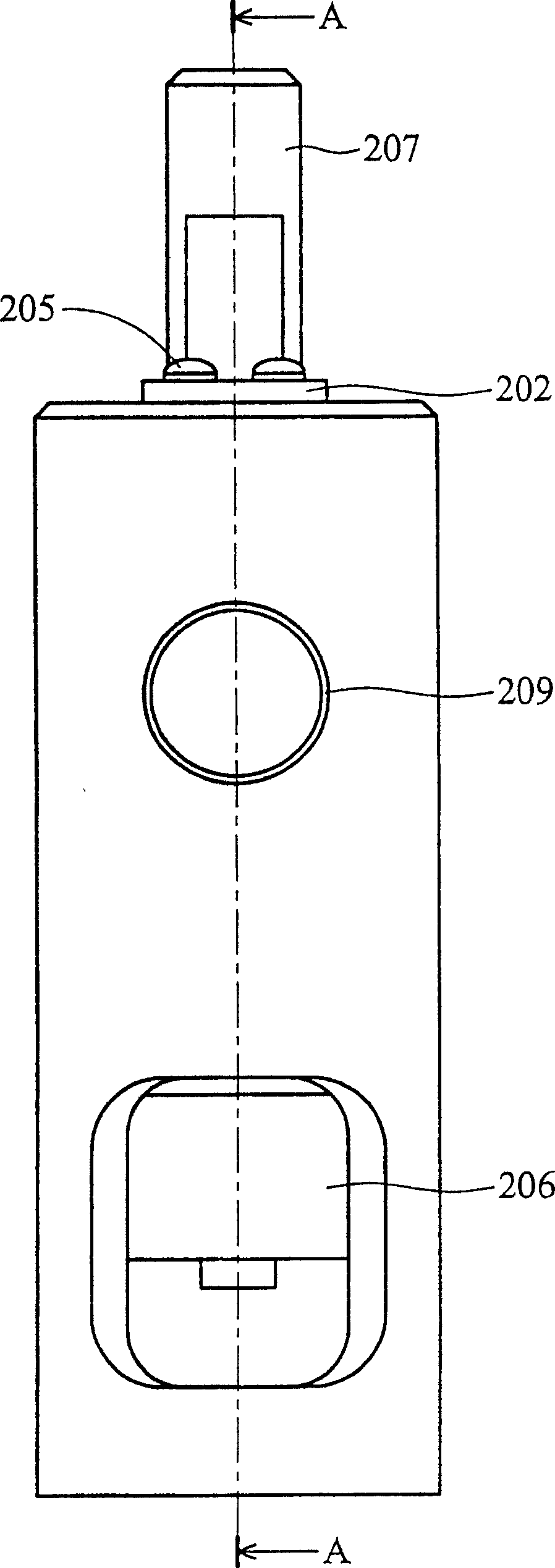
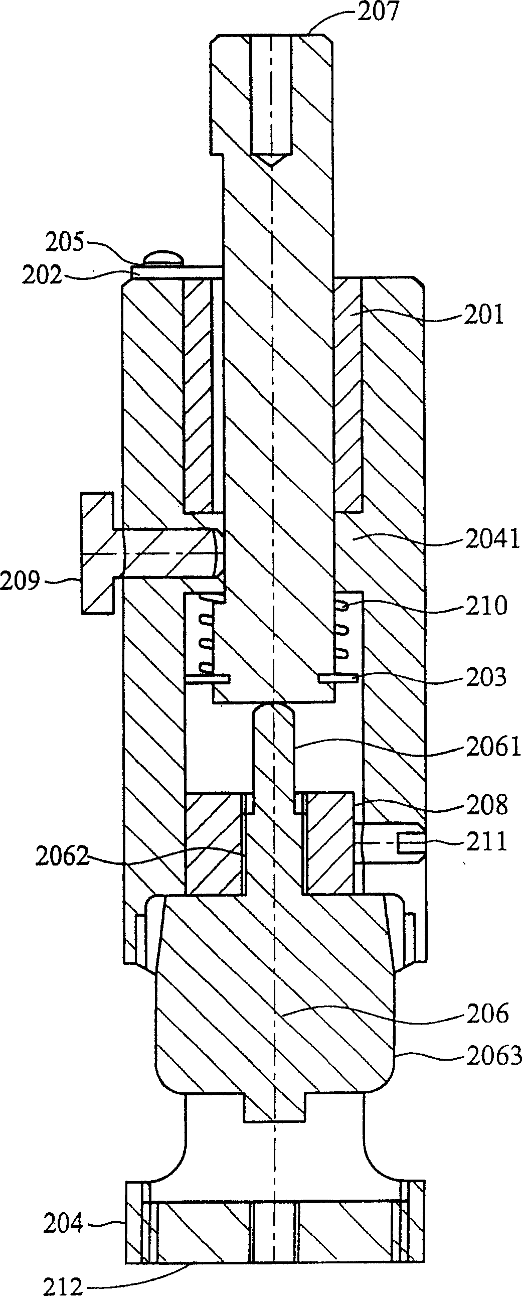
[0031] Such as figure 2 , 3 As shown, it is a preferred embodiment of the present invention, wherein a rod-shaped member 207 is installed in a base 204, and a buckle 203 is arranged at the bottom of the rod-shaped member 207 to fix a compression spring 210 to the rod-shaped member 207, the spring body of the compression spring 210 surrounds the rod member 207 and extends axially, and the other end of the compression spring 210 is in contact with the protrusion 2041 inside the base 204, so that the compression spring 210 is in contact with the buckle 203 and the protruding portion 2041 are compressed.

[0032] A screw mechanism 206 is located in the base 204, the screw mechanism 206 has a helical cylinder 2061, a neck 2062 and a rotating head 2063, rotating the rotating head 2063 of the screw mechanism 206 can make the helical cylinder 2061 move axially...


PUM


Abstract

The invention relates to an optical height adjusting device which comprises a dock, the lower end of which can be mounted on any plane, a rod-like component arranged in the dock, a screw mechanism mounted in the dock, and a compression spring. When rotating the screw mechanism to produce a small displacement for the rod-like component, the compression spring produces a thrust acting force for the rod-like component, making the rod-like component contact the screw mechanism without gaps, thus maintaining accuracy of the height adjusting device.

Description

technical field [0001] The invention relates to a height adjustment device, in particular to an optical height adjustment device. The optical height adjustment device disclosed by the invention is suitable for performing optical experiments or being applied to optical instruments. This height adjustment device can also be used in other fields, such as measuring side, machining, product assembly and so on. If it is combined with a motor and an electric control mechanism, it becomes an electric fine-adjustment height device, which is also quite suitable for the automation industry. Background technique [0002] When conducting optical experiments, it is necessary to use fixtures to hold optical components for alignment or other purposes. When performing alignment, it is necessary to use a height-adjusting device for accurate positioning and alignment. [0003] Ordinary optical parts, such as lenses, are usually clamped by the mirror holder, and fixed on the optical table by ...

Claims


Application Information

Patent Timeline
Patent Type & Authority Applications(China)
IPC IPC(8): G12B5/00
Inventor 石宇森
Owner IND TECH RES INST
Why Eureka
Try Eureka