An assembly fixture for lateral pressure test of sandwich structural panels

A technology for assembling fixtures and sandwich structures, used in measuring devices, instruments, scientific instruments, etc., can solve the problems of secondary damage of the test piece, the deflection can not be maintained in the compression loading condition, and the difficult pressure center alignment, and achieve high safety. , easy to assemble and load, easy to adjust effects

Active Publication Date: 2017-11-03
HARBIN INST OF TECH
View PDF9 Cites 0 Cited by
  • Summary
  • Abstract
  • Description
  • Claims
  • Application Information

AI Technical Summary

Problems solved by technology

[0004] The present invention aims to solve the problem that the large-size (500mm×600mm) skin asymmetrical composite material sandwich panel is difficult to center the center of the pressure center when the lateral pressure performance test is performed, and the deflection is too large to maintain the compression loading condition, resulting in the instant test failure. In order to solve the problem of secondary damage of parts, an assembly fixture for lateral pressure test of sandwich structural panels is proposed

Method used


Image

  • An assembly fixture for lateral pressure test of sandwich structural panels
  • An assembly fixture for lateral pressure test of sandwich structural panels
  • An assembly fixture for lateral pressure test of sandwich structural panels

Examples


specific Embodiment approach 1

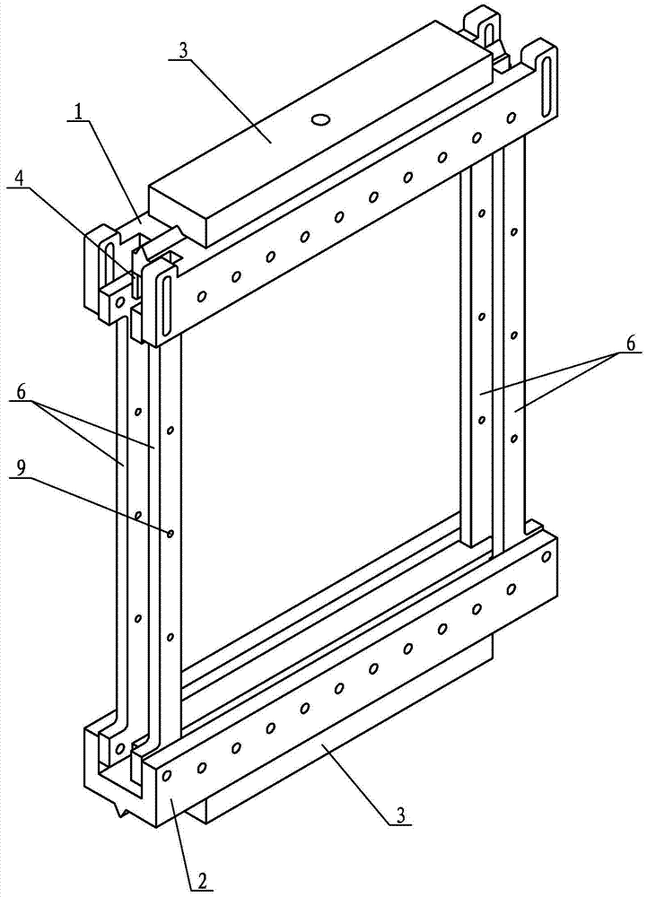
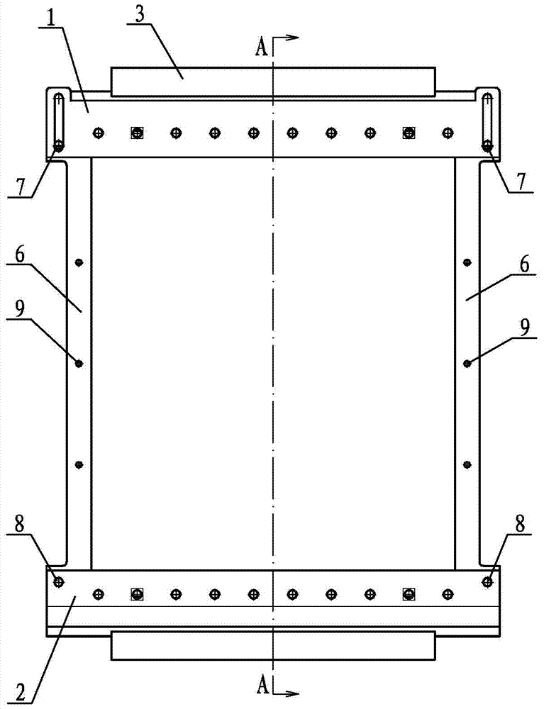
[0039] Specific implementation mode one: combine Figure 1 to Figure 21 Describe this embodiment, this embodiment includes upper chuck 1, lower chuck 2, two end plates 3, two general pads 4, two adjustment pads 5, two long hole connecting elements 7, two round Hole connection element 8, four vertical limit plates 6 and limit connection element 9,

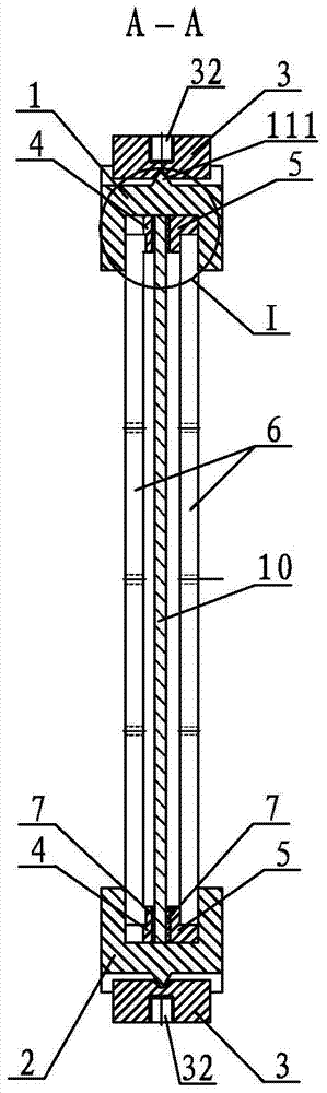
[0040] The cross-section of the upper chuck 1 is H-shaped, which is convenient to be placed horizontally in the opposite direction during assembly. The upper end of the transverse side of the upper chuck 1 is a shallow groove 11, and the lower end is a deep groove 12. The bottom surface of the shallow groove 11 is along the length direction of the central axis. An upper cone flute 111 is provided, and several first upper threaded holes 13 are provided along the length direction on one vertical side of the upper chuck 1 corresponding to the deep groove 12, and the other of the upper chuck 1 corresponding to the deep groove 12 One ve...

specific Embodiment approach 2

[0046] Specific implementation mode two: combination image 3 Describe this embodiment, the width of the deep groove 12 of the upper chuck 1 of this embodiment is equal to the width of the U-shaped groove of the lower chuck 2 . Other components and connections are the same as those in the first embodiment.

specific Embodiment approach 3

[0047] Specific implementation mode three: combination Figure 9 The present embodiment will be described. The taper angle α of the upper tapered flute 111 of the present embodiment is 60°. Other components and connections are the same as those in the second embodiment.


PUM


Abstract

An assembly fixture used for lateral pressure test of a sandwich structure plate, in order to solve the problems of difficulty in centering the pressure center and large deflection when performing a lateral pressure performance test of a large-sized, asymmetrical sandwich panel. The upper chuck and the lower chuck are set up and down, and the deep groove of the upper chuck is set opposite to the U-shaped groove of the lower chuck. Four vertical limit plates are arranged between the upper chuck and the lower chuck in a rectangular shape. The upper end of the limit plate is located in the deep groove, the lower end of each vertical limit plate is located in the U-shaped groove, and the upper end between the two horizontally parallel vertical limit plates is provided with a general spacer and an adjustment spacer. A general spacer and an adjustment spacer are arranged at the lower end between the two parallel vertical limit plates. At the upper and lower ends of the upper chuck and the lower chuck, the upper cone flute on the upper chuck and the lower cone flute on the lower chuck are respectively embedded in corresponding V-shaped grooves. The invention is used for the lateral pressure test of the sandwich structure board.

Description

technical field [0001] The invention relates to a test fixture for a sandwich structure plate, in particular to an assembly fixture for a lateral pressure test of a sandwich structure plate. Background technique [0002] Numerous factors need to be considered in the design of the lateral compression test fixture for sandwich structural panels, such as easy assembly with the testing machine and test piece, achieving moderately well-aligned loading, limiting out-of-plane displacement to meet compression standards, reasonable support constraints, Minimize the difficulty of fixture processing, improve fixture accuracy and service life, and test safety. [0003] In this field, there are many types of fixtures for flat side pressure tests. The assembly is generally to clamp the test piece at the upper and lower ends, adjust the front and rear positions of the test piece through pads, and connect it to the testing machine for compression testing. There are generally three kinds of...

Claims


Application Information

Patent Timeline
Patent Type & Authority Patents(China)
IPC IPC(8): G01N3/04
Inventor 高维成华洲张利猛刘伟刘玥
Owner HARBIN INST OF TECH
Why Eureka
Try Eureka