Device for connecting low-voltage devices

A technology for connecting devices and low-voltage devices, which is applied to the components, connections, coupling devices, etc. of the connecting device to achieve the effect of an effective structure

Inactive Publication Date: 2004-08-18
ABB (SCHWEIZ) AG
View PDF0 Cites 8 Cited by
  • Summary
  • Abstract
  • Description
  • Claims
  • Application Information

AI Technical Summary

Problems solved by technology

Obviously, all these aspects have a negative impact on the overall cost of production and in the use and maintenance of circuit breakers and disconnectors in general

Method used


Image

  • Device for connecting low-voltage devices
  • Device for connecting low-voltage devices
  • Device for connecting low-voltage devices

Examples


Embodiment Construction

[0044] The connection device according to the invention will now be described with reference to the circuit breaker presented in some of the above figures, without these figures being intended to limit its field of application in any way, the connection device being generally applied to low voltage electrical equipment and devices and related accessories. For the purposes of the present invention the term "low voltage electrical equipment" refers to equipment such as circuit breakers, disconnectors, disconnectors and the like.

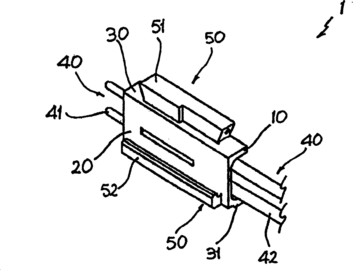
[0045] refer to figure 1 , the connection device for low-voltage electrical equipment and related accessories according to the present invention is generally denoted by reference numeral 1 . The device is substantially a parallelepiped structure having a first pair of surfaces 10 and 11 (not shown) positioned opposite each other, a second pair of surfaces 20 and 21 (not shown) positioned opposite each other , and a third pair of surfaces 30 and 31 (p...


PUM


Abstract

A connection device for low-voltage electrical equipment, such as circuit breakers, disconnectors and isolators, and corresponding accessories, having a substantially parallelepipedal structure with a first pair of faces, a second pair of faces, and a third pair of faces with the faces of each pair set opposite to one another. Each face of said first pair of faces is designed to receive electrical coupling means, whilst at least two faces of said second and third pairs of faces are equipped with mechanical coupling means for connection with said low-voltage equipment, and / or with a further connection device.

Description

technical field [0001] The present invention relates to a connection device for low-voltage equipment and related accessories, and more particularly to a connection device with improved characteristics, especially in terms of modularity and adaptability. Background technique [0002] Low-voltage equipment, especially low-voltage automatic circuit breakers, isolating or disconnecting switches, are devices used for protection or control, usually in industrial electrical systems characterized by operating voltages below 1000V. Automatic circuit breakers are fundamentally different from isolating or disconnecting switches due to their presence in a former device known as a protective relay, which controls the flow of current in the device and supplies power to loads downstream of it, and performs interruption in the event of a fault or hazard. open circuit. For the sake of ease of reading the description and for the sake of brevity, we will subsequently designate the devices me...

Claims


Application Information

Patent Timeline
Patent Type & Authority Applications(China)
IPC IPC(8): H01R9/26
CPCH01R9/2658
Inventor U·斯卡佩利尼L·阿图罗德利因诺岑蒂
Owner ABB (SCHWEIZ) AG
Why Eureka
Try Eureka