Check patentability & draft patents in minutes with Patsnap Eureka AI!

Mobile terminal

A mobile terminal and antenna technology, applied in the field of mobile terminals, can solve problems such as strong directivity and degradation of antenna receiving sensitivity

Inactive Publication Date: 2004-08-18
FUJITSU LTD
View PDF1 Cites 8 Cited by
  • Summary
  • Abstract
  • Description
  • Claims
  • Application Information

AI Technical Summary

Problems solved by technology

[0014] However, in such prior art, a non-directional antenna such as a chip antenna is attached to the human body, and the radiation pattern of the antenna changes due to the influence of the human body, and the radiation pattern is drawn to the human body, thereby deteriorating the receiving sensitivity of the antenna.
In addition, a directional antenna like a rod antenna is installed on the human body. Although it is less affected by the human body, it has strong directivity and can only receive radio waves from satellites in a specific direction.

Method used


Image

  • Mobile terminal
  • Mobile terminal
  • Mobile terminal

Examples


Embodiment Construction

[0049] Embodiments suitable for the present invention will be described below with reference to the drawings.

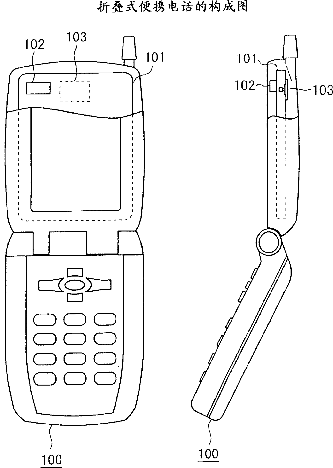
[0050] Below, based on Figure 1 to Figure 4 An embodiment in which the present invention is applied to a foldable mobile phone will be described.

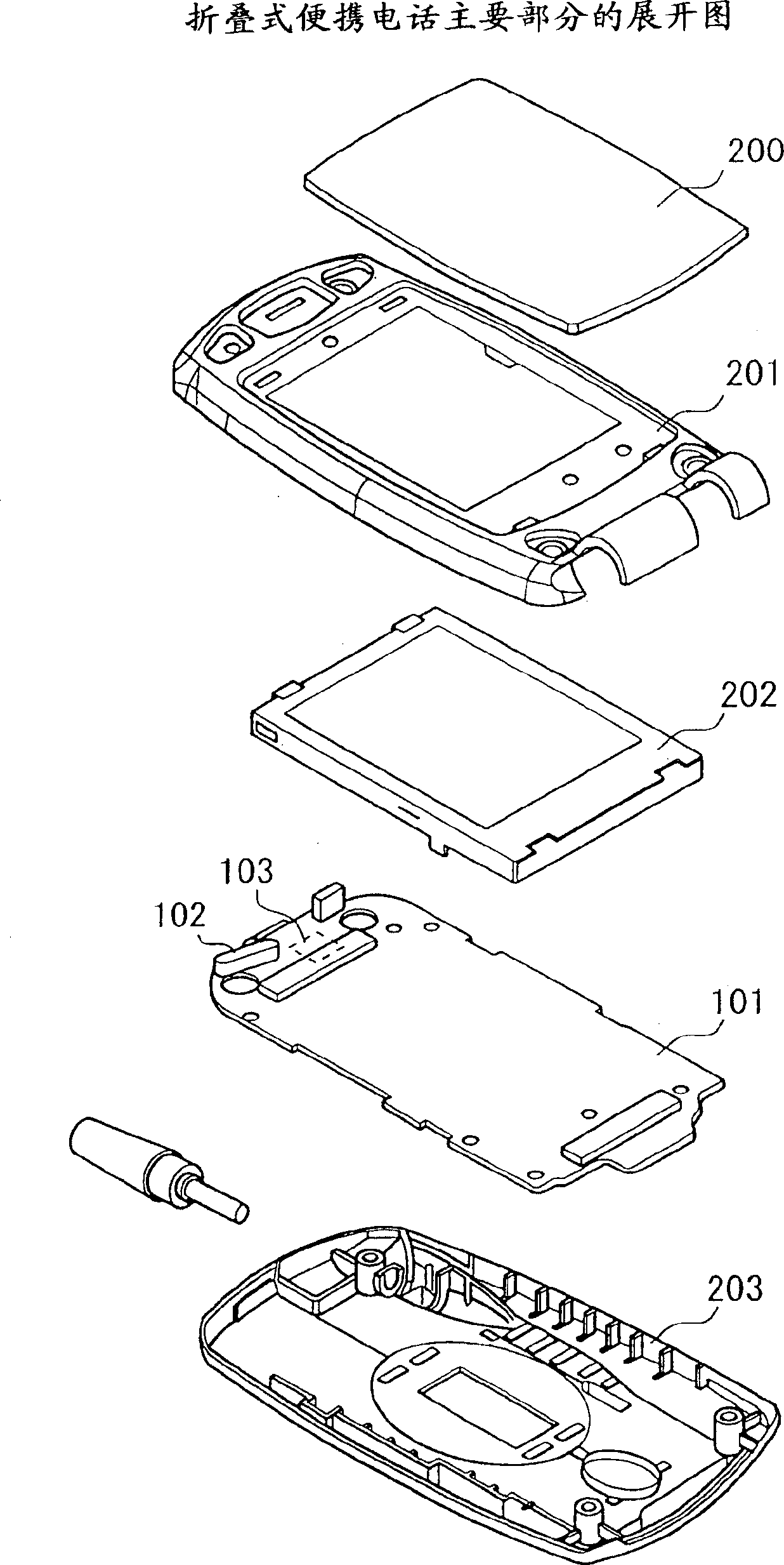
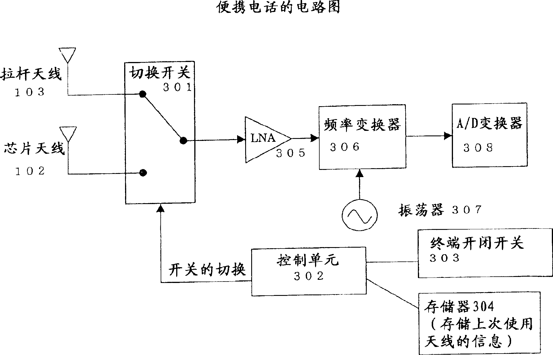
[0051] figure 1 shows the configuration of a foldable mobile phone, figure 2 It is an expanded view of the main part of the foldable mobile phone, image 3 It is a circuit diagram of a folding mobile phone. Figure 4 A flowchart of toggle switch processing is shown.

[0052]

[0053] refer to figure 1 and figure 2 , the configuration of the foldable mobile phone will be described.

[0054] Such as figure 1 As shown, the mobile phone of this embodiment has a structure in which a display main body having a display unit such as a liquid crystal display and a main body on the operation unit side where keys such as buttons are arranged are rotatably coupled by a hinge. figure 1 The shown foldable mobile phone...


PUM


Abstract

A mobile terminal has a first antenna as an omnidirectional antenna, a second antenna as a directional antenna and a switching unit for switching over the antenna for receiving.

Description

technical field [0001] The present invention relates to a mobile terminal that uses GPS (Groubal Positioning Systems) to acquire a position with satellites. Background technique [0002] GPS is a system that calculates the current correct position from orbit and time information by receiving radio waves sent from many artificial satellites placed in the sky above 20,000 kilometers. [0003] Currently, GPS is used in a variety of fields from car driving guidance systems of automobiles to measurement technology. [0004] As such a technology, there is an antenna device used in a car navigation method using GPS, which uses a right-handed circularly polarized antenna and a left-handed circularly polarized A satellite navigation method that detects multipath waves by comparing antenna output levels (see Patent Document 1: JP-A-62-38377). [0005] In addition, GPS is used for emergency notification in mobile phones. [0006] For example, when a mobile phone is used to report No...

Claims


Application Information

Patent Timeline
Patent Type & Authority Applications(China)
IPC IPC(8): H01Q1/24H01Q3/24H01Q21/28H01Q25/00H04B1/38H04B1/3822H04B7/26H04M1/00H04M1/02H04M1/21H04M1/725H04M1/74H04W16/28H04W64/00H04W88/02
CPCH01Q21/28H01Q3/24H01Q1/243H01Q25/002H01Q1/242H04B1/38
Inventor 森信一郎
Owner FUJITSU LTD
Features
  • R&D
  • Intellectual Property
  • Life Sciences
  • Materials
  • Tech Scout
  • Unparalleled Data Quality
  • Higher Quality Content
  • 60% Fewer Hallucinations
Learn More