Expanding apparatus for heat exchange pipe

A heat exchanger, U-tube technology, applied in heat exchange equipment, tubular elements, lighting and heating equipment, etc.

Inactive Publication Date: 2004-08-25
MITSUBISHI ELECTRIC CORP
View PDF1 Cites 27 Cited by
  • Summary
  • Abstract
  • Description
  • Claims
  • Application Information

AI Technical Summary

Problems solved by technology

[0005] However, in the conventional tube expander, when the number of fins is large, or the shape of the fin collar is changed, and the relationship between the load on the fin collar and the amount of shrinkage changes, etc., There will be the following problems, that is, the buckling of the fin collar, the heat sink that overlaps in the stacking direction is in close contact with the heat sink, the air path is blocked, and defective products are produced.

Method used


Image

  • Expanding apparatus for heat exchange pipe
  • Expanding apparatus for heat exchange pipe
  • Expanding apparatus for heat exchange pipe

Examples


Embodiment approach 1

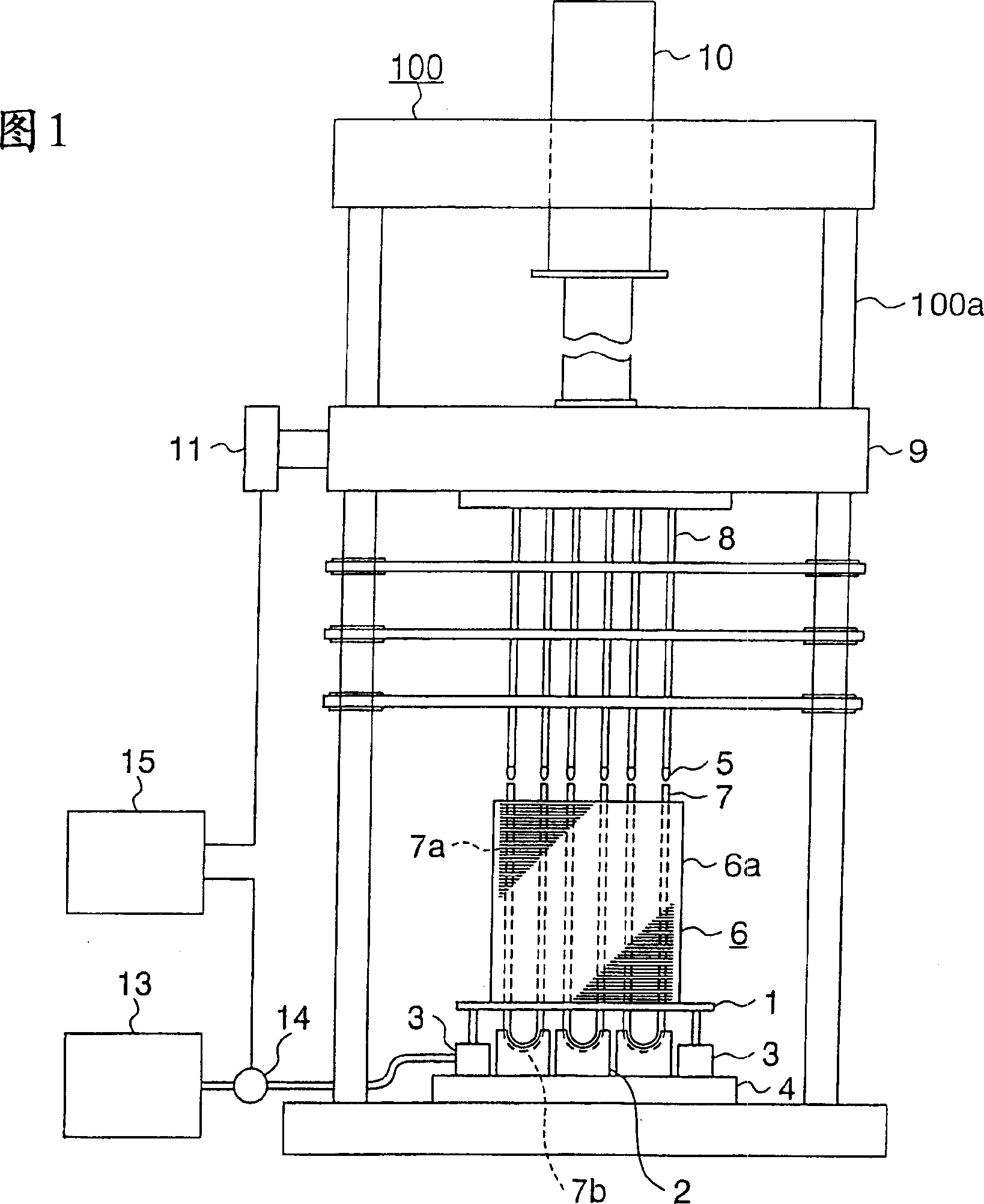
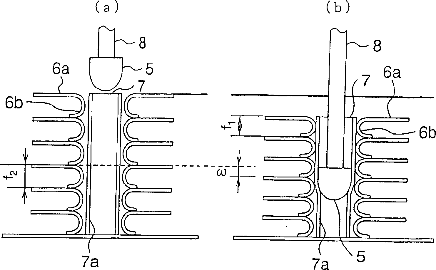
[0024] Fig. 1 is a front view showing the overall configuration of a pipe expanding device according to Embodiment 1 of the present invention. In FIG. 1 , a heat exchanger 6 is placed in a pipe expander 100 . The heat exchanger 6 is used, for example, as a fin-and-tube heat exchanger of an air conditioner or the like. The heat exchanger 6 is composed of a plurality of fins 6a stacked in the vertical direction in FIG. 1 and a plurality of U-shaped tubes 7 passing through the fins 6a in the stacking direction. The U-shaped pipe 7 is composed of two linear portions 7a bent in a substantially U-shape and extending in parallel, and a curved portion 7b connecting the ends thereof. A plurality of U-shaped tubes 7 are inserted through the stacked cooling fins 6a from one side, the straight portion 7a passes through the cooling fins 6a, and the curved portion 7b protrudes from the side end. A hole through which the U-shaped tube 7 passes is formed on the main surface of the heat sink...

Embodiment approach 2

[0045] Figure 8 It is a relational figure which shows the point which lowers the fin receiver 1 which concerns on Embodiment 2 of this invention. The vertical axis represents the descending amount of the fin receiver 1, and the horizontal axis represents the number of fins 6a after tube expansion. The solid line in the figure represents the descending amount of the fin receiver 1 during the expansion process.

[0046] In this embodiment 2, as Figure 8 As shown, at a certain speed, it drops to point X in the initial stage of pipe expansion, and at a speed higher than the initial stage, it drops to point Y in the middle stage of pipe expansion. In this way, since the increase ratio of the cumulative shrinkage amount tends to increase in the later stage of pipe expansion compared with the initial stage, it decreases from point Y to point Z with a further increase in speed. The descending mode of the finned receiver 1 set in this way, the descending amount of the finned recei...

Embodiment approach 3

[0059] Figure 11 It is a front view showing the configuration of main parts of the pipe expanding device according to Embodiment 3 of the present invention. In this embodiment, both ends of the fin receiver 1 are supported by elastic bodies through which the guide posts 17 pass. As the elastic body, for example, a coil spring 18 set in compression is used. When the mandrel 8 is lowered, the billet 5 is inserted into the upper end of the U-shaped pipe 7, and pipe expansion starts. When the billet 5 further descends and reaches the fin 6a group, the compressive load applied to the fin collar 6b ​​before pipe expansion starts to accumulate. Since the compressive load is transmitted from the fin receiver 1 to the coil spring 18 and is used to compress the coil spring 18 along the guide column 17, the compressive load accumulated on the fin collar 6 before tube expansion can be reduced. After pipe expansion is completed, if the mandrel 8 is raised to extract the billet 5 from t...


PUM


Abstract

Provided is a pipe expansion device of a heat exchanger wherein no buckling of fin collars is generated, and the heat exchanger is constituted of radiating fins with a constant distance. The pipe expansion device is provided with: mandrels 8 having billets 5 at their respective tips; a reciprocating body 9 supporting the back ends of the mandrels 8 and being supported to be freely reciprocated in an axial direction of hair pin pipe linear parts 7a; a pressurizing cylinder 10 which elevates the reciprocating body 9, and pipe-expands, as a pressurizing driving source, the linear parts 7a in such a manner that the billets 5 are pressed into the hair pin pipe linear parts 7a; hair pin receivers 2 supporting curved parts 7b of the hair pin pipes 7; a fin receiver 1 supporting the bottom part of the radiating fins 6a superimposed with several sheets; and a hydraulic cylinder 3 as a means for elevating the fin receiver 1. The cylinder 3 sends down the fin receiver 1 to a prescribed position when the mandrels 8 descend, and the billets 5 start getting into the hair pin pipes 7.

Description

technical field [0001] The invention relates to a tube expanding device. The tube expanding device expands the tube relative to a heat exchanger, and fixes a plurality of cooling fins integrally. The heat exchanger is composed of a plurality of cooling fins and a plurality of tubes interspersed therein. , especially related to the improved tube expansion device of the heat exchanger, the improved tube expansion device of the heat exchanger will not cause the fins overlapping in the stacking direction to be in close contact with the fins due to the buckling of the fin collar , Cut off the wind path and produce substandard products. Background technique [0002] In the past, a tube expanding device has, for example, a structure in which, with respect to a heat exchanger constituted by a plurality of cooling fins and a plurality of tubes inserted through the cooling fins, the tubes inserted therein are expanded, and multiple tubes are integrally fixed. sheet heat sink. [000...

Claims


Application Information

Patent Timeline
Patent Type & Authority Applications(China)
IPC IPC(8): F28F1/32B21D39/20B21D53/08
CPCY10T29/53113Y10T29/49375B23P15/26Y10T29/53122Y10T29/53117B21D53/085Y10T29/49368
Inventor 中出口真治中岛伸治田中满高田浩明
Owner MITSUBISHI ELECTRIC CORP
Why Eureka
Try Eureka