A processing and assembling method of an interference stop fit rotary body component

An assembly method and interference fit technology are applied in metal processing, metal processing equipment, and parts of pumping devices for elastic fluids, etc., which can solve the hidden dangers of safe operation of aero-engines and gas turbines, and cannot ensure that there is no residual iron filings, Difficult control of iron filings and other problems, to achieve the effect of solving mechanical processing interference, no hidden iron filings hidden dangers in blind cavity, and reducing mechanical processing procedures

Active Publication Date: 2021-03-12
AECC AVIATION POWER CO LTD
View PDF6 Cites 0 Cited by
  • Summary
  • Abstract
  • Description
  • Claims
  • Application Information

AI Technical Summary

Problems solved by technology

In the original technology, in order to solve this problem, the bottom hole of the precision connection hole is processed first when the compressor hub is processed, and after a certain margin is reserved, combined processing (reaming) is performed after the compressor hub is assembled. Due to the structural limitation of the rotor, combined machining cannot be performed due to interference after assembly, and there are many blind cavities in the compressor rotor. The safe operation of engines and gas turbines has brought certain hidden dangers

Method used


Image

  • A processing and assembling method of an interference stop fit rotary body component
  • A processing and assembling method of an interference stop fit rotary body component
  • A processing and assembling method of an interference stop fit rotary body component

Examples


Embodiment Construction

[0035] The present invention will be described in detail below in conjunction with the embodiments and the accompanying drawings.

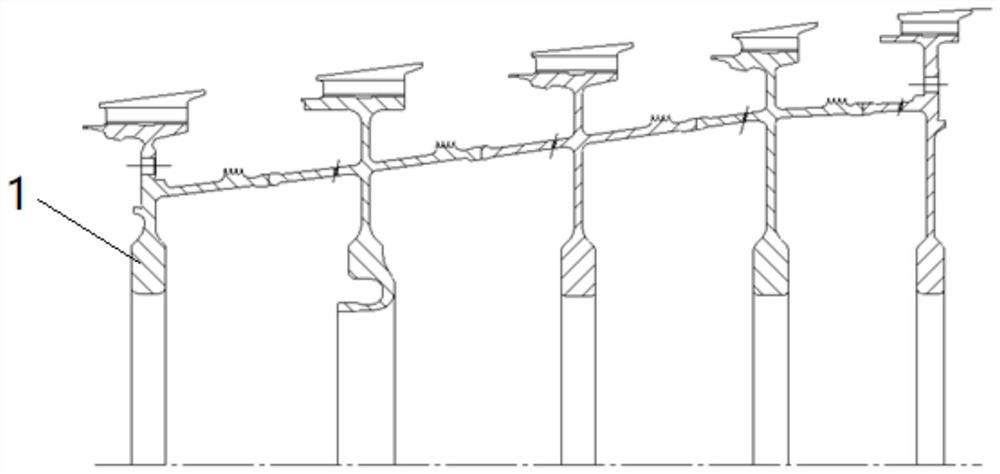
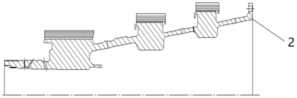
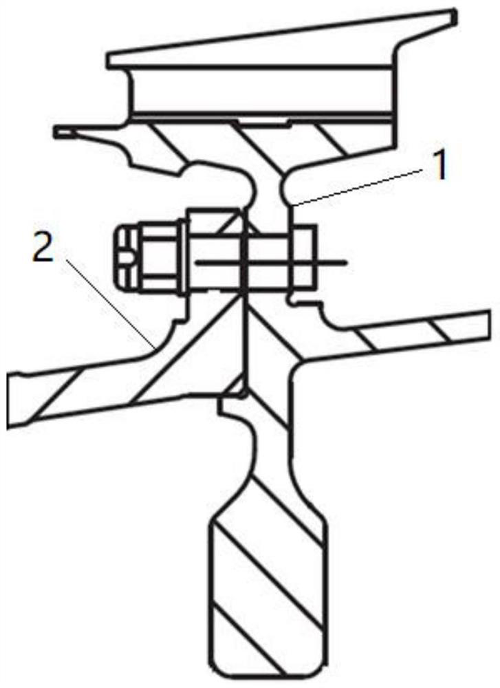
[0036] A method for processing and assembling a revolving body assembly with an interference fit. The revolving body assembly includes a first revolving body and a second revolving body. The diameter D1 of the first revolving body is larger than the diameter D2 of the second revolving body. Bolt connection holes are provided on the mating end surfaces of the first rotator and the second rotator, and the first rotator and the second rotator pass interference fit at the seam and are connected by bolts; including the following steps:

[0037] Step 1, process the first rotating body, measure and record the spigot diameter D1, and then process the connection hole according to the designed pitch circle diameter D;

[0038] Step 2, process the second rotating body, measure and record the spigot diameter D2;

[0039] Step 3, calculate the seam fit interf...


PUM


Abstract

The invention discloses a machining and assembling method of an interference rabbet matching rotary body assembly. The rotary body assembly comprises a first rotary body and a second rotary body. Therabbet diameter D1 of the first rotary body is larger than the rabbet diameter D2 of the second rotary body, and a bolt connecting hole is formed in the matching end face of the first rotary body andthe second rotary body, the first rotary body is in interference fit with the second rotary body through a rabbet position and connected though bolts; and the rabbet interference fit amount is firstlycalculated, the second rotary body is heated, the first rotary body and the second rotary body are assembled, and finally the two rotary bodies are connected with the bolts. The machining method caneffectively eliminate the misalignment of precision connecting holes of the rotary body assembly caused by the assembly deformation and the resulting parts scratching, the assembly accuracy of the rotary body assembly is ensured, and no internal stress is realized after the assembly is completed; and the machining cleanliness is higher, no hidden danger of blind cavities and iron chips is realized, and the problem of machining interference of part compressor rotor assemblies can be solved.

Description

technical field [0001] The invention belongs to the field of assembly of mechanical parts, and in particular relates to a processing and assembly method of an interference stop fit rotating body assembly. Background technique [0002] As an important part of aero-engines and gas turbines, the compressor rotor is composed of the compressor drum through joint fit and bolt connection. When working, it rotates at high speed and bears complex and huge stress. In order to ensure the reliable and safe operation of aero-engines and gas turbines. How to make the evenly distributed position on the compressor drum require a group of 0.03mm (the specific number of holes is determined according to the strength calculation) and the precision connection holes can maintain the same pitch circle of the holes after the compressor drum assembly is assembled to meet the bolts The matching requirements of assembly dimensions is a technical problem to be solved. [0003] During the assembly pr...

Claims


Application Information

Patent Timeline
Patent Type & Authority Patents(China)
IPC IPC(8): B23P11/02F04D29/26
CPCB23P11/025F04D29/26
Inventor 陈伟席锋李进韩燕垒张文斌侯莉张婵张东旭
Owner AECC AVIATION POWER CO LTD
Why Eureka
Try Eureka