Electromagnetic disc brake and traction machine provided with same

A technology of brakes and electro-magnetic disks, applied in the field of traction machines, can solve the problems of direct contact between the brake disks and the motor housing, difficulty in adjusting the brakes, etc., so as to eliminate low machining accuracy, avoid low machining accuracy, and reduce materials. cost effect

Active Publication Date: 2014-11-12
浙江西子富沃德电机有限公司
View PDF8 Cites 4 Cited by
  • Summary
  • Abstract
  • Description
  • Claims
  • Application Information

AI Technical Summary

Problems solved by technology

[0008] Although the brake structure disclosed in this utility model can be reduced in size in the axial direction, there is still the problem that the brake disc is directly in contact with the motor housing, and the air gap of the brake (the distance between the brake disc and the adjacent components) It is also difficult to adjust

Method used


Image

  • Electromagnetic disc brake and traction machine provided with same
  • Electromagnetic disc brake and traction machine provided with same

Examples


Embodiment Construction

[0037] The electromagnetic disk brake of the present invention and the traction machine equipped with the electromagnetic disk brake will be described in detail below in conjunction with the accompanying drawings.

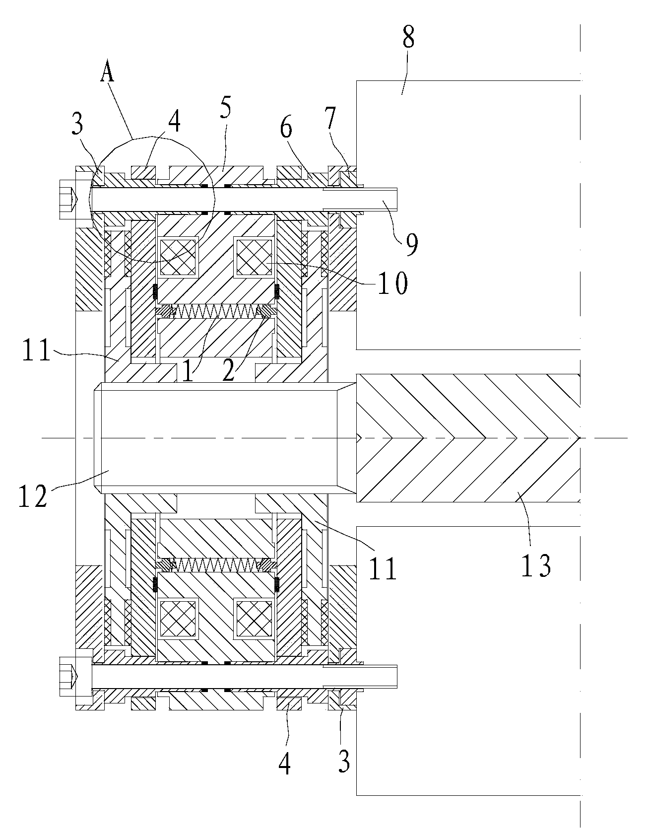
[0038] Such as figure 1 Shown, a kind of electromagnetic disk type brake comprises the static iron core 5 and moving iron core 4 that interact by electromagnetic force, and the brake disc 11 that is fixed with main shaft 13 (between the rotating shaft 12 of brake disc 11 and the main shaft 13 of motor fixedly connected by splines) and the brake plate 3 that cooperates with the moving iron core 4 to clamp the brake disc 11.

[0039] There are two moving iron cores 4 located on both sides of the static iron core 5 respectively, and two sets of brake discs 11 and brake plates 3 are arranged outside the corresponding moving iron cores 4 in turn.

[0040] There are two coil windings 10, and there are slots for accommodating the two coil windings 10 respectively. The tw...


PUM


Abstract

The invention relates to an electromagnetic disc brake and a traction machine provided with the electromagnetic disc brake. The electromagnetic disc brake disclosed by the invention comprises a stationary iron core and two movable iron cores through electromagnetic interaction, two brake discs fixed with a main shaft, and two brake plates which are matched with the movable iron cores and are used for clamping the brake discs, wherein the two movable iron cores are respectively positioned on the two sides of the stationary iron core, and a brake spring is arranged between each of the two movable iron core and the stationary iron core; a coil winding acting on each movable iron core is arranged on the stationary iron core; the two brake discs and the two brake plates are arranged outside the corresponding movable iron cores in sequence. The stationary iron core, the two movable iron cores and the two brake plates are fastened in a penetrating mode through a connecting sleeve, unthreaded holes penetrating through the connecting sleeve are formed in the stationary iron core, the two movable iron cores and the two brake plates, the connecting sleeve and the stationary iron core are connected through interference fit, and the connecting sleeve and the brake plates are pressed together through riveting. The electromagnetic disc brake is smaller in size, safe and convenient to use and convenient to maintain.

Description

technical field [0001] The invention relates to the technical field of motors, in particular to an electromagnet brake and a traction machine equipped with the electromagnet brake. Background technique [0002] The elevator traction machine is the power equipment of the elevator, which is used to convey and transmit power to make the elevator run. It is usually composed of a motor, a brake, a coupling, a reduction box, and a traction wheel. [0003] The traction wire rope goes around the traction sheave, one end of which is connected to the car, and the other end is connected to the counterweight. The motor drives the traction sheave to rotate, relying on the friction between the traction wire rope and the traction sheave to drive the car and the counterweight to move up and down. For the elevator traction machine, the brake is an important safety component, and the electromagnetic disc brake is a relatively common brake form in the prior art. [0004] At present, there are...

Claims


Application Information

Patent Timeline
Patent Type & Authority Applications(China)
IPC IPC(8): B66D5/14B66B11/04
Inventor 祝海生梅金丽周红星
Owner 浙江西子富沃德电机有限公司
Why Eureka
Try Eureka