Motion control apparatus and method for automotive vehicle

A motion control and vehicle technology, applied in the direction of automatic steering control components, control devices, joint control, etc., can solve problems such as adverse effects of rear wheel steering angles

Inactive Publication Date: 2004-08-25
NISSAN MOTOR CO LTD
View PDF4 Cites 15 Cited by
  • Summary
  • Abstract
  • Description
  • Claims
  • Application Information

AI Technical Summary

Problems solved by technology

Thus, it is likely to have an adverse effect on the rear wheel steering angle

Method used


Image

  • Motion control apparatus and method for automotive vehicle
  • Motion control apparatus and method for automotive vehicle
  • Motion control apparatus and method for automotive vehicle

Examples


no. 1 example

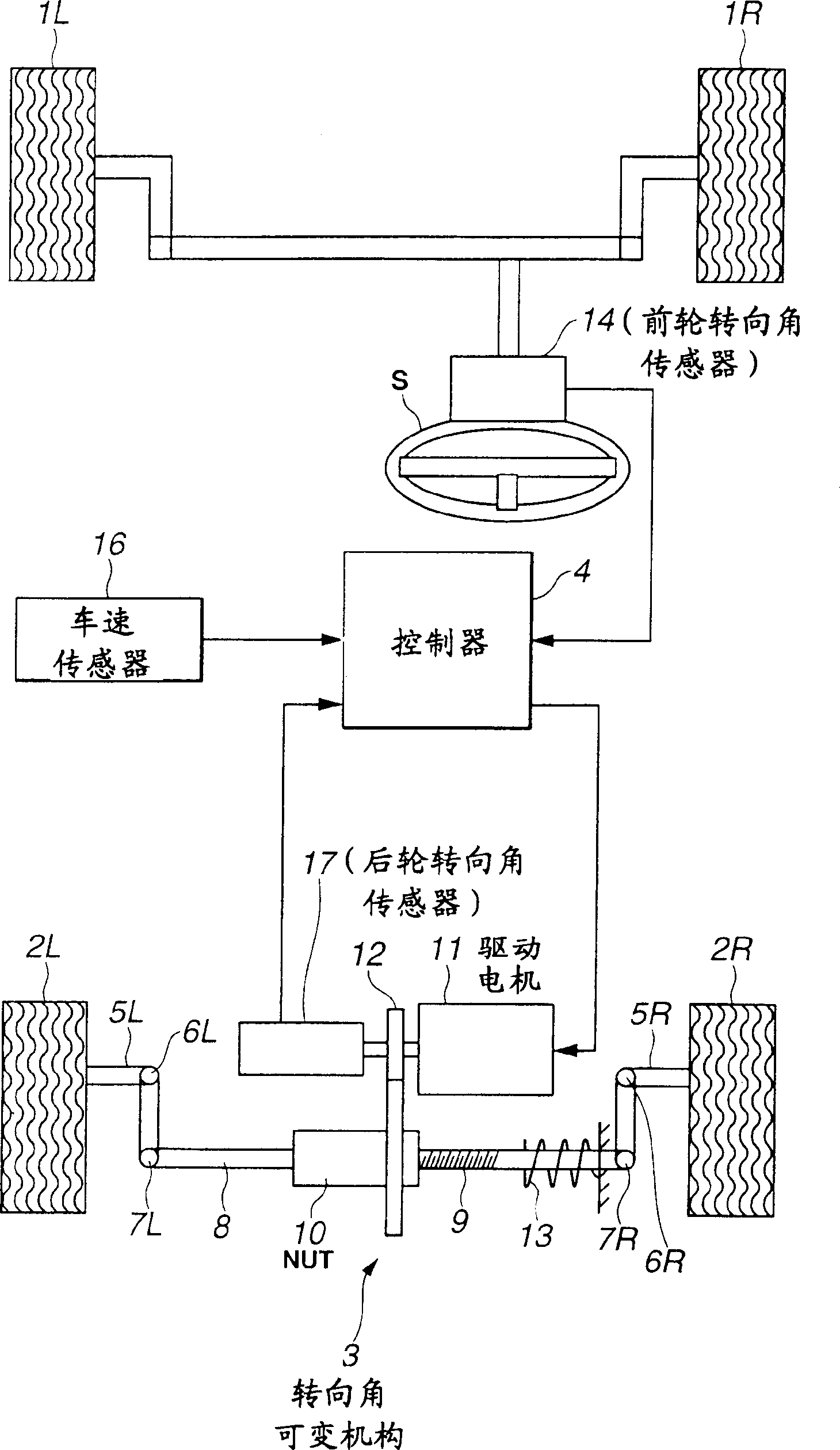
[0022] figure 1 is an overall system configuration diagram showing the basic configuration of the vehicle motion control apparatus in the first preferred embodiment according to the present invention.

[0023] The steering angle variable mechanism 3 includes: knuckle arms 5L and 5R connected to the left rear wheel 2L and right rear wheel 2R; king pin axles 6L and 6R; ball joints 7L and 7R; 5L and 5R, and a connecting rod (tierod) 8 formed around the spherical joints 7L and 7R; a sliding screw (slip screw) 9 formed on the connecting rod 8; Nut 10, sliding screw 9 formed on the connecting rod by means of kingpin shaft 6L, 6R and ball joint 7L, 7R between steering knuckle arms 5L and 5R; on the rotating shaft and meshes with the outer teeth of the nut 10. The rotational drive of the drive motor 11 moves the link 8 in the left-rear direction to steer the left-right rear wheels 2L and 2R. Note that reference numeral 13 denotes a return spring that returns the link 8 to the neutr...


PUM


Abstract

In vehicular motion control apparatus and method, a vehicle speed variation rate limiter is provided to place a vehicle speed variation rate limitation on a detection value (V) of a vehicle speed and varying a vehicle speed variation rate limiter value in accordance with the detection value (theta) of the vehicular steering angle, at the vehicular motion target value calculation, using an output of the vehicular speed variation rate limiter for a map reference vehicle speed (Vmap) and, at the control command value calculation, using the output of the vehicular speed variation rate limiter to the detection value of the vehicle speed for a control command value calculation purpose.

Description

technical field [0001] The present invention relates to a motor vehicle motion control apparatus and method capable of controlling vehicle motion during steering maneuver inputs at the front wheels. Background technique [0002] Japanese Patent Application First Publication No. HeiSei 10-007010 published on January 13, 1998 (corresponding to US Patent No. 5,957,987 issued on September 28, 1999) exemplifies a previously proposed vehicle motion control apparatus. In the Japanese Patent Application First Publication filed above, the vehicle yaw rate and the like are controlled during the steering operation (maneuvering), thereby maintaining the stability of the vehicle during the steering wheel operation. Specifically, the target yaw rate of the response characteristic related to the planar motion of the vehicle is calculated according to the steering angle and the vehicle speed corresponding to the predetermined response characteristic, and the yaw rate generated on the vehicl...

Claims


Application Information

Patent Timeline
Patent Type & Authority Applications(China)
IPC IPC(8): B62D6/00B62D7/14B62D7/15B62D101/00B62D113/00
CPCB62D7/159
Inventor 堤淳二数藤秀树
Owner NISSAN MOTOR CO LTD
Why Eureka
Try Eureka