
Humidity sensing arrangement for microwave oven with vented fume hood

A sensing device and microwave oven technology, applied in the field of microwave ovens, can solve problems such as inability to omit, inaccurate humidity, etc., and achieve the effects of smooth discharge, reduction in the number of parts, and cost reduction

Inactive Publication Date: 2004-08-25
LG ELECTRONICS (TIANJIN) APPLIANCES CO LTD
View PDF0 Cites 3 Cited by
  • Summary
  • Abstract
  • Description
  • Claims
  • Application Information

AI Technical Summary

Problems solved by technology

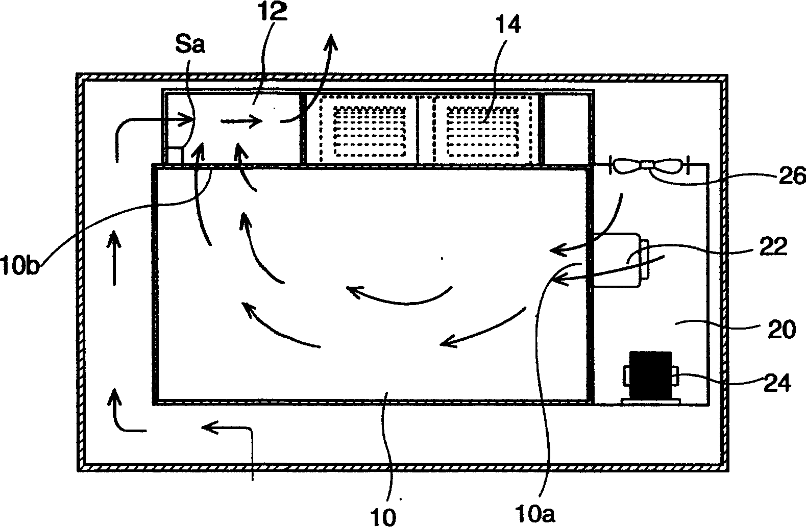
[0007] The disadvantage of the above-mentioned humidity sensing device for a microwave oven with a ventilation hood is that the air flow discharged through the exhaust port 10b is driven by the fan 26, so in order to measure the humidity of the air inside the heating chamber 10, the fan 26 is Indispensable components that cannot be omitted
[0008] In addition, in the inside of the heating chamber 10, although the air enters the heating chamber through the air inlet 10a, if the heating chamber 10 has other gaps, it is impossible for all the water vapor in the heating chamber to pass through the exhaust port. discharge, so the humidity sensor Sa measures the humidity inaccurately

Method used


Image

  • Humidity sensing arrangement for microwave oven with vented fume hood
  • Humidity sensing arrangement for microwave oven with vented fume hood
  • Humidity sensing arrangement for microwave oven with vented fume hood

Examples


Embodiment Construction

[0022] Below in conjunction with accompanying drawing and specific embodiment the present invention is described in further detail:

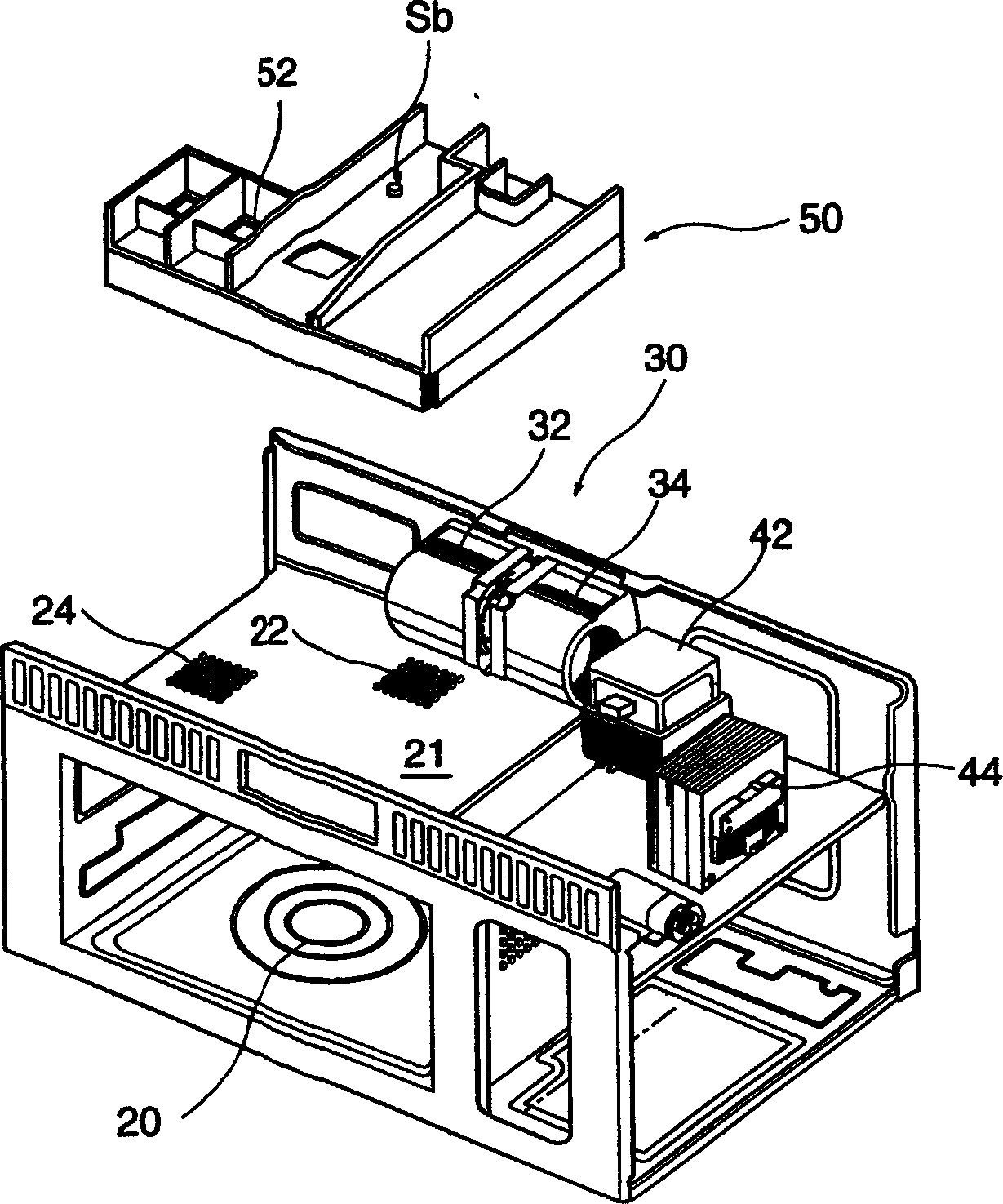
[0023] like figure 2 As shown, the present invention is used for the humidity sensing device of the microwave oven with ventilation hood and comprises: the cavity 21 above the heating chamber, the exhaust motor assembly 30 arranged at the rear of the cavity 21 above the heating chamber, the exhaust motor assembly arranged at the 30 is connected to the exhaust port 22 of the heating chamber 20, and the front part of the cavity 21 above the heating chamber is connected to the air inlet 24 of the heating chamber 20, and is arranged near the exhaust port 22 to measure the humidity of the exhausted air. Humidity sensor Sb.

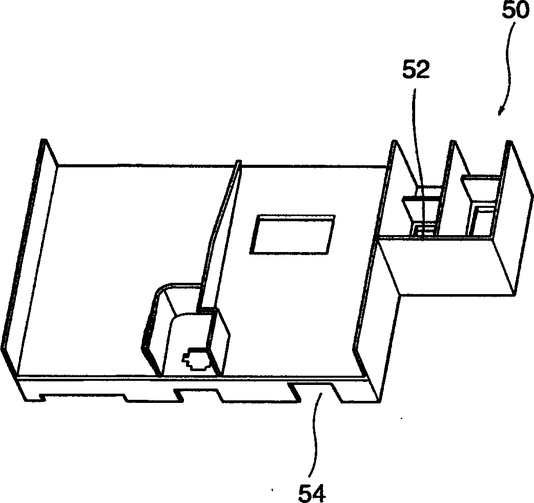
[0024] The cavity 21 above the heating chamber is provided with an air channel 50 for guiding air flow; the humidity sensor Sb is arranged on the air channel 50 corresponding to the upper part of the exhaust port 22 .

[0025]...


PUM


Abstract

The present invention discloses a humidity preception device of microwaven oven with a ventilation cover. Said invention includes: upper cavity of heating chamber, exhaust motor component placed in the rear portion of upper cavity of heating chamber, exhaust hole palced near by exhaust motor component and communicated with the heating chamber, air inlet placed in the front of upper cavity of heating chamber and communicated with heating chamber and humidity sensor placed near by exhaust hole and used for determining humidity of exhausted air. In the described upper cavity of heating chamber an air channel for guiding air flow is set, and the humidity sensor Sb is placed on the air channel correspondent to upper portion of exhaust hole.

Description

technical field [0001] The invention relates to a microwave oven with a ventilation hood, in particular to a humidity sensing device for the microwave oven with a ventilation hood. Background technique [0002] A microwave oven with a ventilated hood is hereinafter referred to as a microwave oven. In addition to using microwaves to heat food, it can also discharge the smoke generated by the oven at the bottom of the microwave oven. [0003] like figure 1 As shown, the existing microwave oven with a ventilation hood generally includes: a heating chamber 10 for heating food and an electric control chamber 20 arranged on the side of the heating chamber 10 . The electric control room 20 is provided with electrical components for emitting microwaves to the heating chamber 10 , such as a magnetron 22 for generating microwaves and a step-up transformer 24 for inputting power signals to the magnetron 22 . [0004] In order to dissipate heat from the magnetron 22 and the step-up tr...

Claims


Application Information

Patent Timeline
Patent Type & Authority Applications(China)
IPC IPC(8): F24C7/02F24C7/08
Inventor 李承勲
Owner LG ELECTRONICS (TIANJIN) APPLIANCES CO LTD
Learn More