
Noise elimination structure of vacuum cleaner

A technology for vacuum cleaners and exhaust outlets, which is applied to vacuum cleaners, cleaning equipment, household appliances, etc. It can solve problems such as high-frequency noise and large noise volume, and achieve the effects of improving work performance, smooth exhaust, and reducing noise

Inactive Publication Date: 2008-11-12
LG ELECTRONICS (TIANJIN) APPLIANCES CO LTD
View PDF0 Cites 3 Cited by
  • Summary
  • Abstract
  • Description
  • Claims
  • Application Information

AI Technical Summary

Problems solved by technology

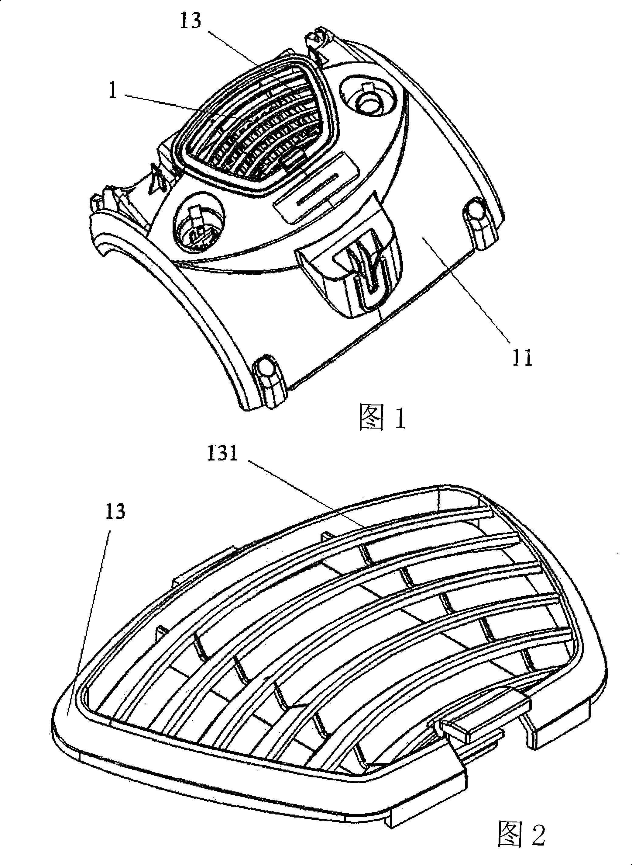
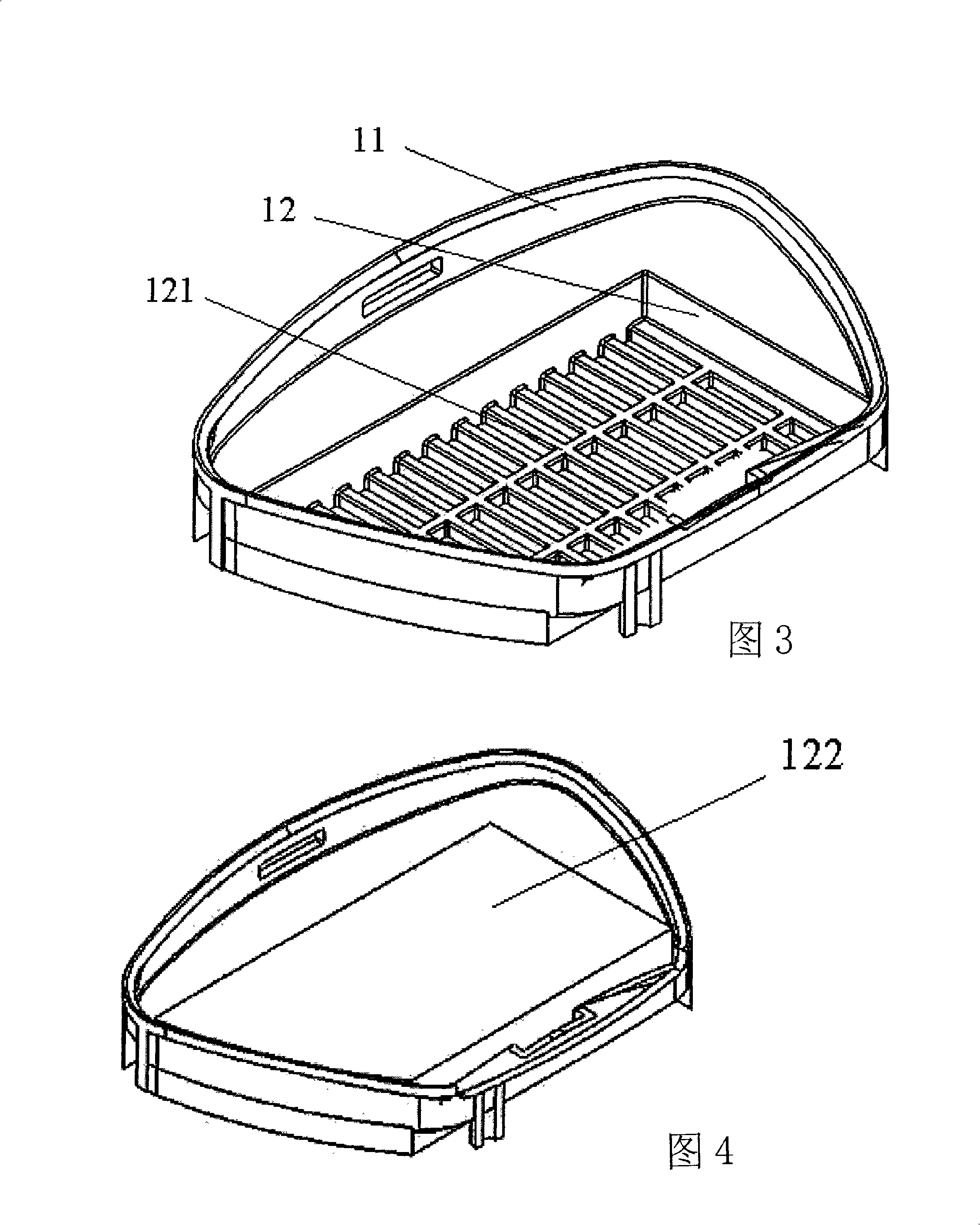
The pad body 122 is made of sound-absorbing materials. This design structure can reduce the exhaust noise generated in the exhaust part to a certain extent, and reduce the noise near the vacuum cleaner body, but it cannot effectively reduce the noise as a whole. The noise when the vacuum cleaner is working, under normal circumstances, measured by the sound level meter, the standard measuring point of the vacuum cleaner (that is, 1 meter directly above the vacuum cleaner body), the noise is about 75dB
[0008] It can be seen from the above that the existing components and structures for reducing noise of vacuum cleaners are limited to reducing the air noise generated in the suction part and the discharge part to a certain extent, and cannot solve the problem of high-frequency noise generated when the motor and fan vibrate. Therefore, it is necessary to design a structure that can reduce the high-frequency noise generated by the vibration of the motor and fan, so as to overcome the defect of high noise in the existing vacuum cleaner in an all-round way, effectively improve the working performance of the vacuum cleaner, and make the vacuum The working environment of the vacuum cleaner is more ideal

Method used


Image

  • Noise elimination structure of vacuum cleaner
  • Noise elimination structure of vacuum cleaner
  • Noise elimination structure of vacuum cleaner

Examples


Embodiment Construction

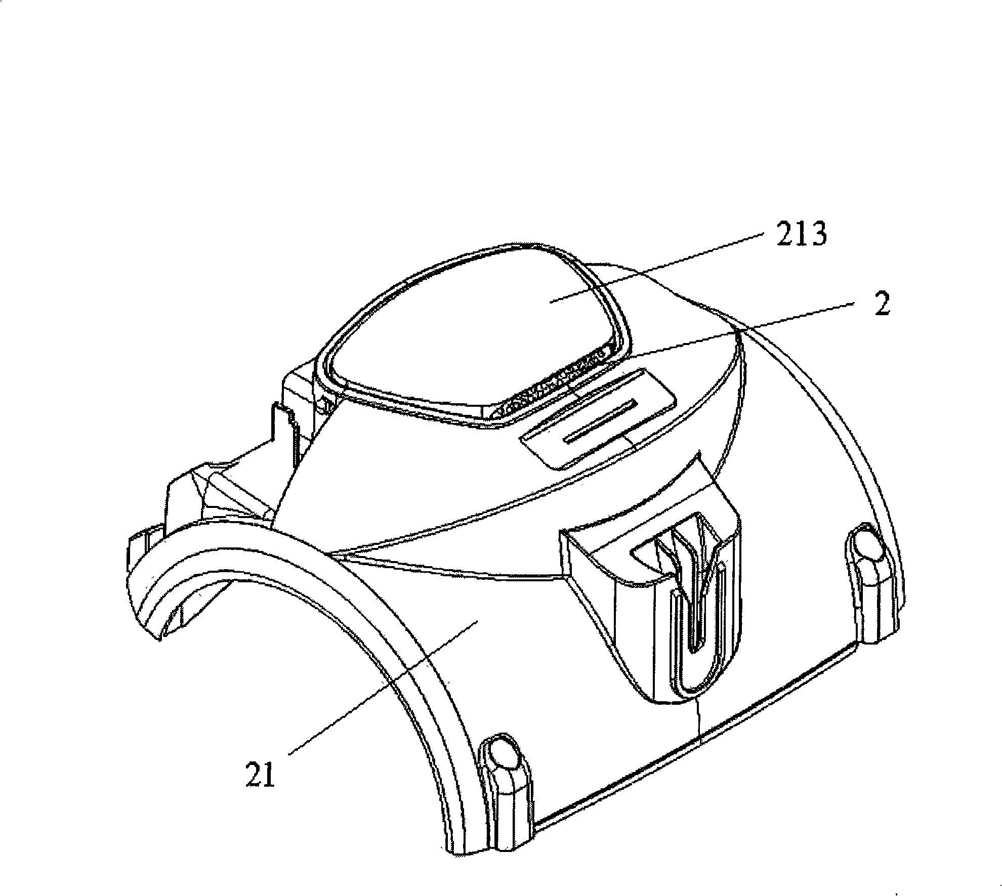
[0033] refer to Figure 5 , as shown in Fig. 6 and Fig. 7, the noise reduction structure of the vacuum cleaner of the present invention includes an upper casing 21, a groove 211 is integrally formed on the upper casing 21, a cover body 213 is arranged on the groove 211, and a cover body 213 is arranged on the groove 211. The pad body 215 is placed; the improvement is that several air outlets 212 are provided at the bottom of the groove 211; several air outlets 214 are provided on the side of the rear end of the cover 213.

[0034] The noise reduction structure of the vacuum cleaner of the present invention, wherein, several exhaust ports 212 provided at the bottom of the groove 211 are integrally formed on the bottom of the groove 211, and the opening area of ​​each exhaust port 212 is less than or equal to the vibration frequency of the motor or fan. A quarter of the wavelength; several exhaust ports 214 provided on the rear end side of the cover body 213 are integrally formed...


PUM


Abstract

The invention provides a muffler structure of a vacuum dust cleaner, comprising an upper casing having an integrally-molded groove with a cover for receiving a liner, wherein the bottom of the groove is provided with a plurality of air outlets, and the opening area of each air outlet is less than or equal to one quarter of the wavelength corresponding to the vibration frequency of the motor or the fan; the side surface on the rear end of the casing is provided with a plurality of air outlets, and the opening area of each air outlet is less than or equal to one quarter of the wavelength corresponding to the vibration frequency of the motor or the fan; the liner in the groove is arranged movably, and can efficiently absorb the high-frequency noise caused by vibration of the motor and the fan, improve the sound quality of the vacuum dust cleaner in operation, and reduce the total noise of the vacuum dust cleaner, so that the noise of the vacuum dust cleaner in operation can be controlled within about 70dB at standard measuring point.

Description

technical field [0001] The invention relates to a vacuum cleaner, in particular to a noise reduction structure of the vacuum cleaner which is arranged on the top of the vacuum cleaner, effectively reduces the high-frequency squeal generated by the motor and the fan during operation, and improves the sound quality of the vacuum cleaner during operation. Background technique [0002] A vacuum cleaner is a device that sucks dust. It generates a strong suction in the body of the vacuum cleaner. Under the action of the strong suction, the dust accumulated in the area or part that needs to be cleaned is forcibly inhaled through the suction nozzle. Because it absorbs dust more Thorough, high efficiency, and can protect the environment. Therefore, in recent years, vacuum cleaners have been widely used by people, especially in cleaning work in general homes, offices, conference halls, etc., especially for cleaning carpets, sofas, In the cleaning operation of the corner of the wall an...

Claims


Application Information

Patent Timeline
IPC IPC(8): A47L5/00
Inventor 肖宗亮任光智
Owner LG ELECTRONICS (TIANJIN) APPLIANCES CO LTD
Learn More