Combined electric cooking utensil
A combined type and cooker technology, which is applied to household appliances, household stoves/stoves, electric heating fuels, etc., can solve the problems of large size of the electric rice cooker, scattered heating cookers on the stove surface, and easy damage to the pot body. The appearance surface is easier to keep as new for a long time, the appearance surface is easy to keep as new for a long time, and the appearance surface is easy to clean.
- Summary
- Abstract
- Description
- Claims
- Application Information
AI Technical Summary
Problems solved by technology
Method used
Image
Examples
Embodiment 1
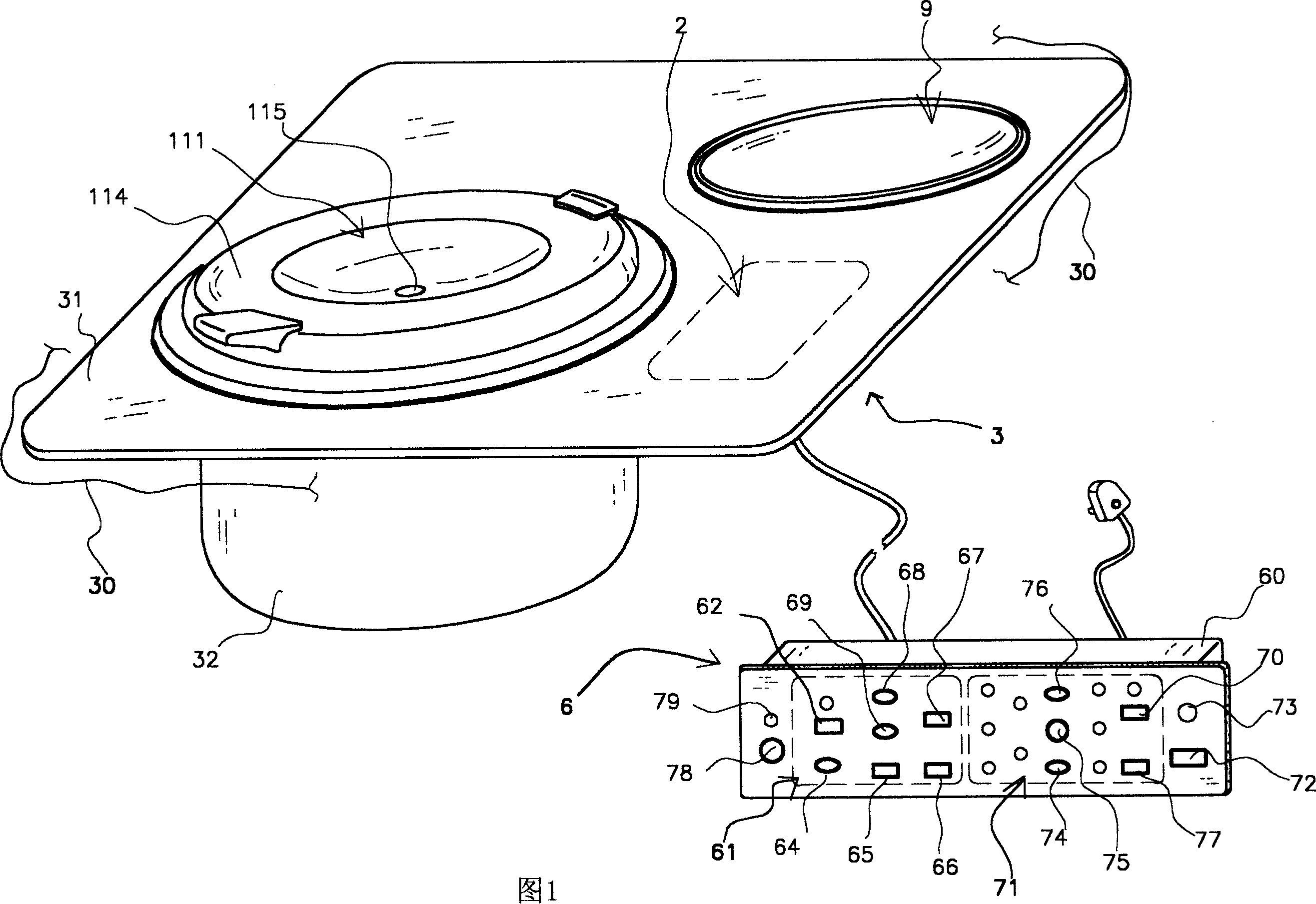
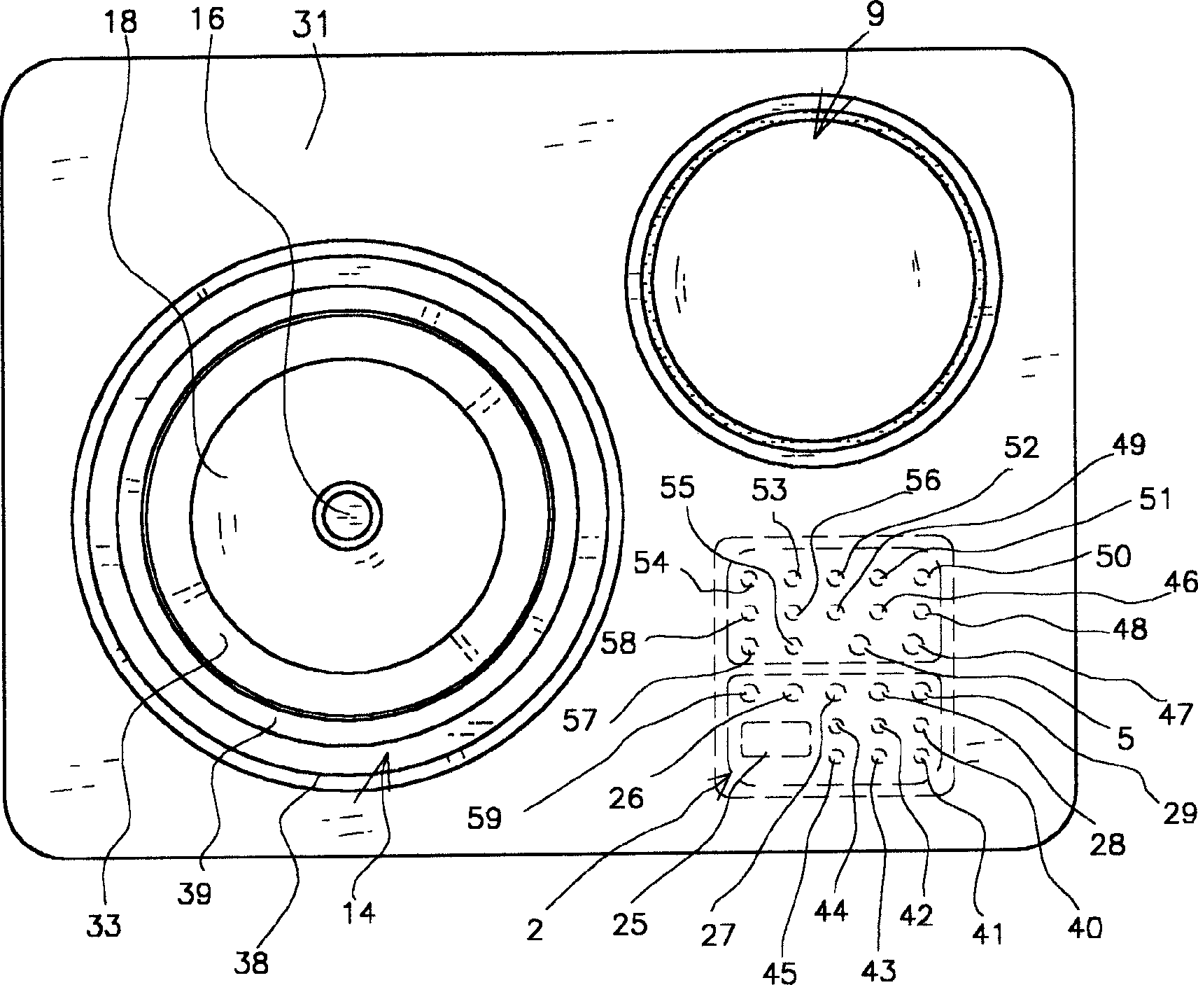
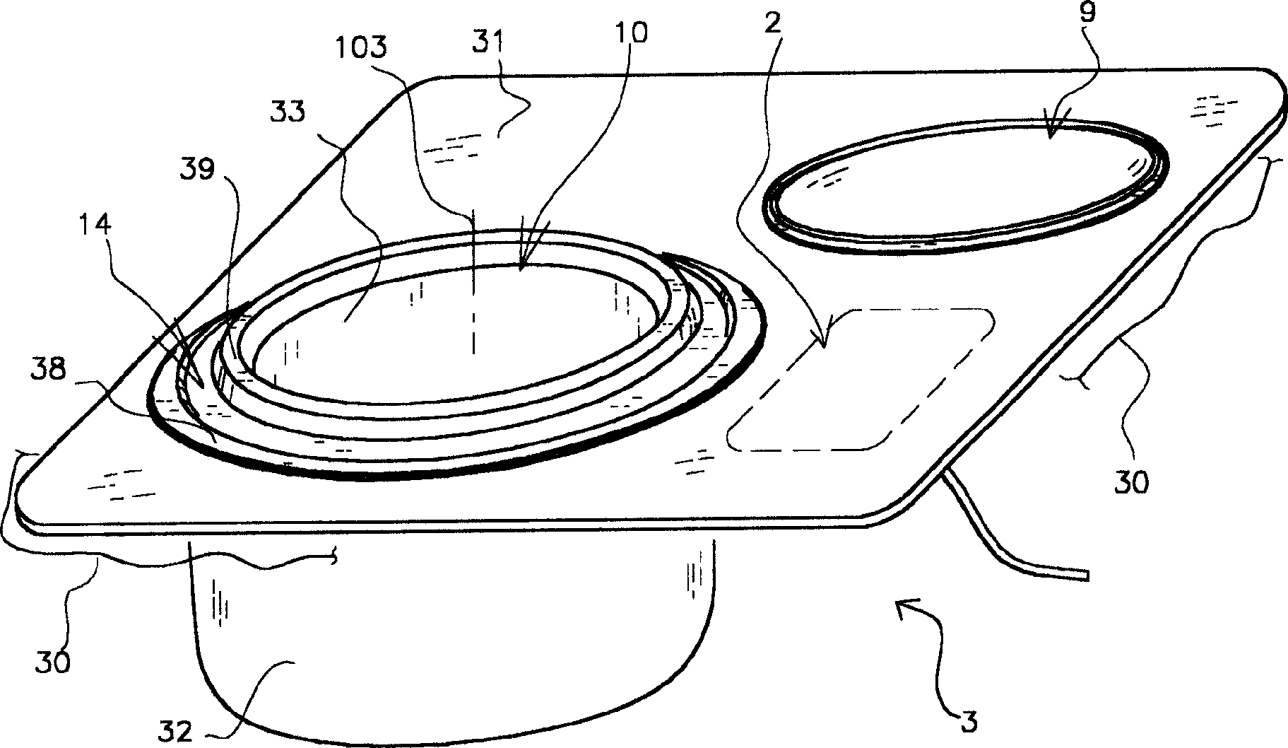
[0053] A combined cooker of the present invention, referring to accompanying drawings 1 to 6, 10, 11 and 21, has a cooker body 3 and two electric heating units, one of which is a rice cooker unit, and the other is a cooker electric heating unit. heating unit. The above-mentioned electric cooker unit has an inner pot placement part 10 in the shape of a cylindrical cavity with an upper opening, an inner pot 37 is arranged in the cavity shape of the inner pot placement part, and an electric heating device 18 is arranged at the lower part of the cavity shape of the inner pot placement part. The control device includes a control operation part 61 of an operating element, a temperature sensing part 16 with a temperature sensing element, an electric drive display part 2 with a display element, and a cover 114 on the inner pot 37; The electric heating device 9 in the range body 3 has a control operation part 71 and an electrically driven display part 2 with a display element.
[0054...
Embodiment 2
[0070] The structure of the combined cooker of this embodiment is basically the same as that of Embodiment 1, which is generally shown in FIGS. 1-6, 10 and 11, and its structural features are shown in FIG. In this embodiment, for example, as shown in Fig. 7, an inner peripheral mouth 4 at the through hole 12 has a metal ring disc guard ring 11 with a downwardly extending edge, and the guard ring 11 also has an annular groove 14 on the top; the lining in embodiment 1 The ring 35 is replaced by the annular upper lining ring 104 shown in FIG. 7 ; the shell in Embodiment 1 is replaced by the shell 33 with an upper opening and an inclined edge as shown in FIG. 7 . The lower side of the substrate 31 which is a glass plate shown in FIG. 7 has an adhesive layer 15 which is a colored layer.
[0071] When assembling the rice cooker unit of the cooker body of the combined electric cooker, the straight cylinder of the upper lining ring 104 is fitted in the through hole 12 of the base plat...
Embodiment 3
[0074] The structure of the combined cooker of this embodiment is basically the same as that of Embodiment 1, and roughly refer to Figures 1 to 6, 10, and 11, and its structural features are as follows Figure 8 shown. This example Figure 8 As shown in the grommet 11 of a solid metal ring disk located at the through hole 12, the grommet 11 also has an annular groove 14 on the upper end surface; the back ring 35 in the embodiment 1 is Figure 8 The shown upper lining ring 109, the lower lining ring 97 are replaced; the shell in embodiment 1 is replaced by Figure 8 Shown instead is a shell 33 with an inverted upper opening along the sides. Figure 8 The cooker body shown has an adhesive layer 15 of a metal plate on the underside of the substrate 31 of a glass plate, and the adhesive layer 15 of the metal plate is adhered to the underside of the substrate 31 with a medium 17 .
[0075] When the electric rice cooker unit of the stove body of the combined electric cooker is pa...
PUM
 Abstract
Description
Claims
Application Information
 - R&D
- Intellectual Property
- Life Sciences
- Materials
- Tech Scout
- Unparalleled Data Quality
- Higher Quality Content
- 60% Fewer Hallucinations
Browse by: Latest US Patents, China's latest patents, Technical Efficacy Thesaurus, Application Domain, Technology Topic, Popular Technical Reports.
© 2025 PatSnap. All rights reserved.Legal|Privacy policy|Modern Slavery Act Transparency Statement|Sitemap|About US| Contact US: help@patsnap.com


