Information estimation method, information recording/reproducing equipment, information reproducing equipment and information recordingmedium
A signal evaluation and information recording technology, applied in optical recording/reproduction, digital recording/reproduction, digital signal error detection/correction, etc., can solve the problems of inability to evaluate signal quality and inability to accurately estimate error rate, etc.
- Summary
- Abstract
- Description
- Claims
- Application Information
AI Technical Summary
Problems solved by technology
Method used
Image
Examples
Embodiment 1
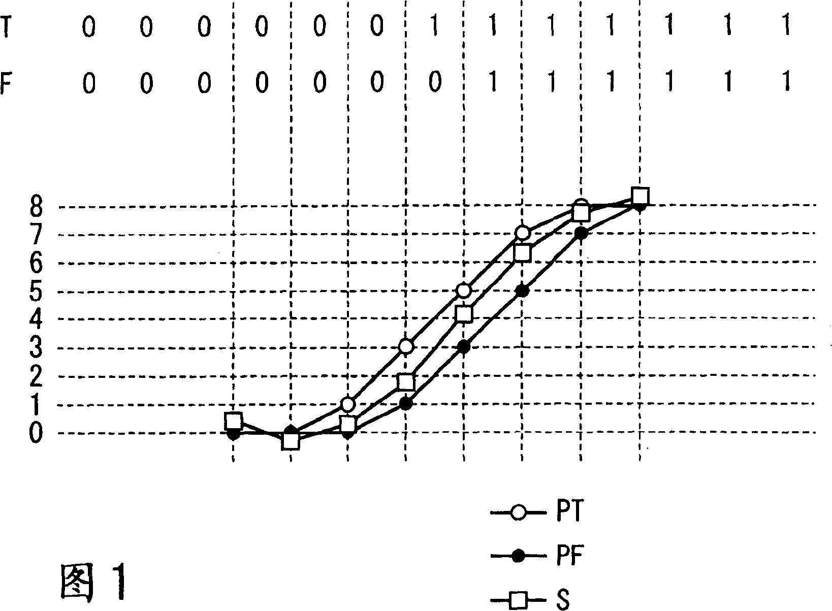
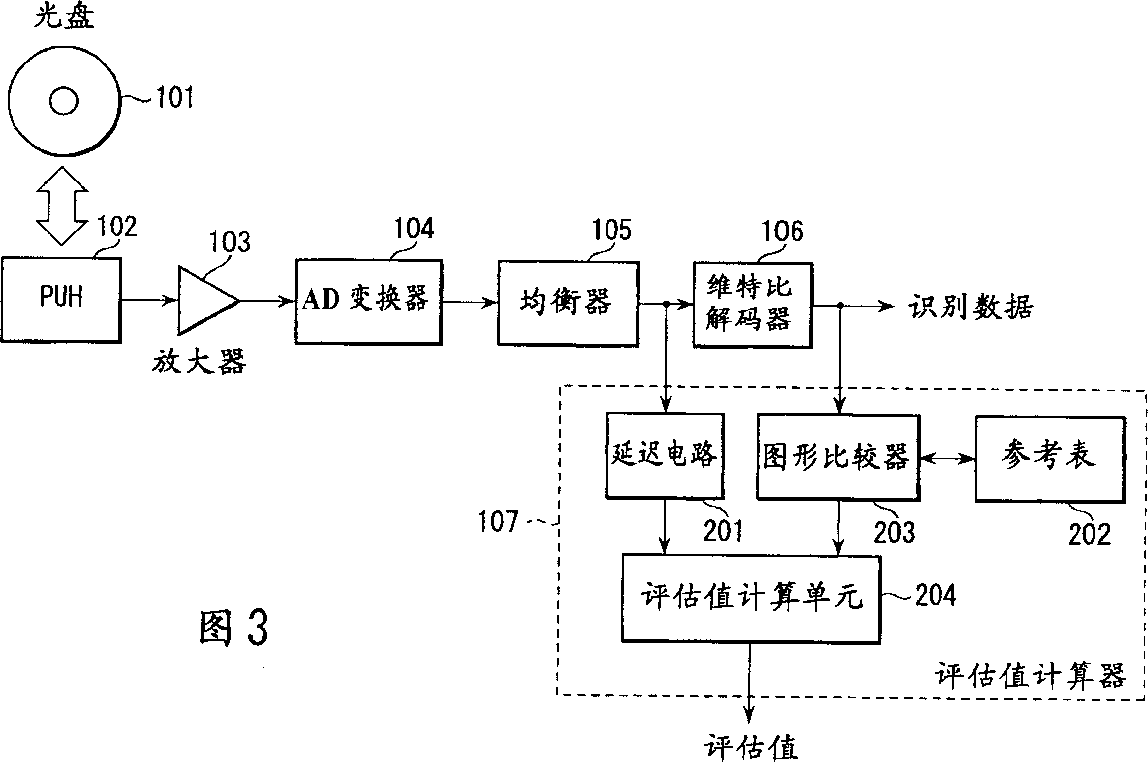
[0060] Fig. 3 is a block diagram showing the configuration of one embodiment of the present invention. Referring to FIG. 3, an optical head device (PUH) 102 reads out information recorded on an information recording medium (optical disc) 101 as marks and spaces, obtaining a weak analog signal. Amplifier 103 amplifies the weak analog signal to a sufficiently high level. An analog-to-digital (AD) converter 104 converts the amplified analog signal into a digital reproduction signal. The equalizer 105 equalizes the digital reproduced signal so that the digital reproduced signal has a waveform corresponding to the PR characteristic to be used (hereinafter, the digital reproduced signal having such a waveform is simply referred to as "equalized signal"). Then, this equalized signal is sent to the Viterbi decoder 106 and the evaluation value calculator 107 . Viterbi decoder 106 decodes the equalized signal according to the Viterbi algorithm to obtain binary identification data. Th...
Embodiment 2
[0088] Figure 5A waveform adjustment circuit is shown that uses the above-mentioned estimated value or an intermediate calculation result for calculating the estimated value. exist Figure 5 In , the same reference numerals as in FIG. 3 denote similar or corresponding structural units. exist Figure 5 In the shown system, the recording waveform generator 301 adjusts the recording parameters in such a manner that the evaluation value or the intermediate calculation result satisfies a predetermined value. The adjusted recording data is sent to the optical head device 102 .
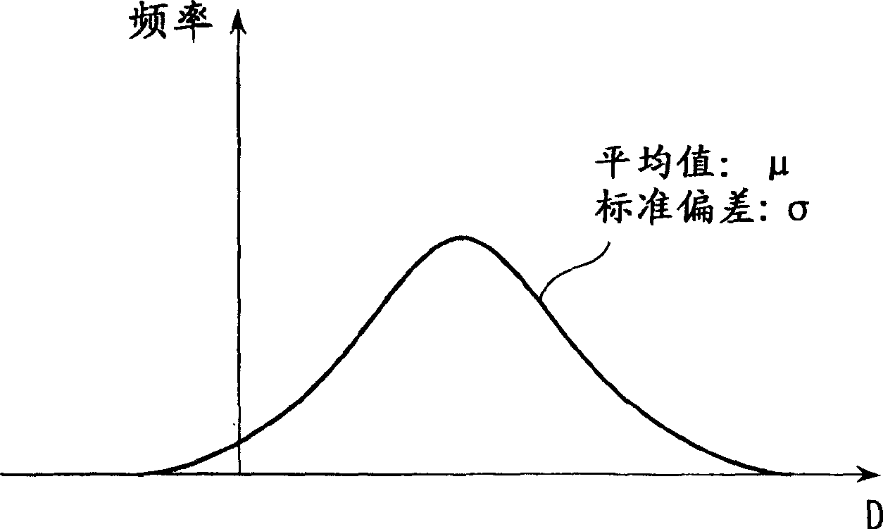
[0089] A description will be given of how to adjust the recording parameters with reference to the reference tables shown in Tables (1-1) and (1-2) and using the mean values and standard deviations calculated for each group. We assume the mean to be μ and the standard deviation to be σ. In this case, the larger the value of Z (=μ / σ), the lower the probability that the pattern T will be mistaken for t...
Embodiment 3
[0092] 6 and 7 show third and fourth embodiments of the present invention. Before describing the embodiment shown in FIG. 7, the embodiment shown in FIG. 6 will be described. Referring to FIG. 6, an optical head device (PUH) 102 reads out information recorded on an information recording medium (optical disc) 101 as marks and spaces, obtaining a weak analog signal. Amplifier 103 amplifies the weak analog signal to a sufficiently high level. An analog-to-digital (AD) converter 104 converts the amplified analog signal into a digital reproduction signal. The equalizer 105 equalizes the digital reproduction signal so that the digital reproduction signal has a waveform corresponding to the PR characteristic to be used. Then, the equalized signal is sent to the Viterbi decoder 106 , the first evaluation value calculator 107 and the second evaluation value calculator 108 .
[0093] Viterbi decoder 106 decodes the equalized signal according to the Viterbi algorithm to obtain binary ...
PUM
 Abstract
Description
Claims
Application Information
 - R&D
- Intellectual Property
- Life Sciences
- Materials
- Tech Scout
- Unparalleled Data Quality
- Higher Quality Content
- 60% Fewer Hallucinations
Browse by: Latest US Patents, China's latest patents, Technical Efficacy Thesaurus, Application Domain, Technology Topic, Popular Technical Reports.
© 2025 PatSnap. All rights reserved.Legal|Privacy policy|Modern Slavery Act Transparency Statement|Sitemap|About US| Contact US: help@patsnap.com


