
Single-phase induction motor

An induction motor, single-phase technology, applied in the field of motors, can solve problems such as increased current loss and decreased motor efficiency

Inactive Publication Date: 2004-09-08
LG ELECTRONICS INC
View PDF0 Cites 9 Cited by
  • Summary
  • Abstract
  • Description
  • Claims
  • Application Information

AI Technical Summary

Problems solved by technology

At this time, since the primary copper loss is generated from the stator coil and the secondary copper loss is generated from the conductor bar of the rotor, the current loss increases and the efficiency of the motor decreases.

Method used


Image

  • Single-phase induction motor
  • Single-phase induction motor
  • Single-phase induction motor

Examples


Embodiment Construction

[0032] Reference will now be made in detail to some preferred embodiments of the invention, examples of which are illustrated in the accompanying drawings.

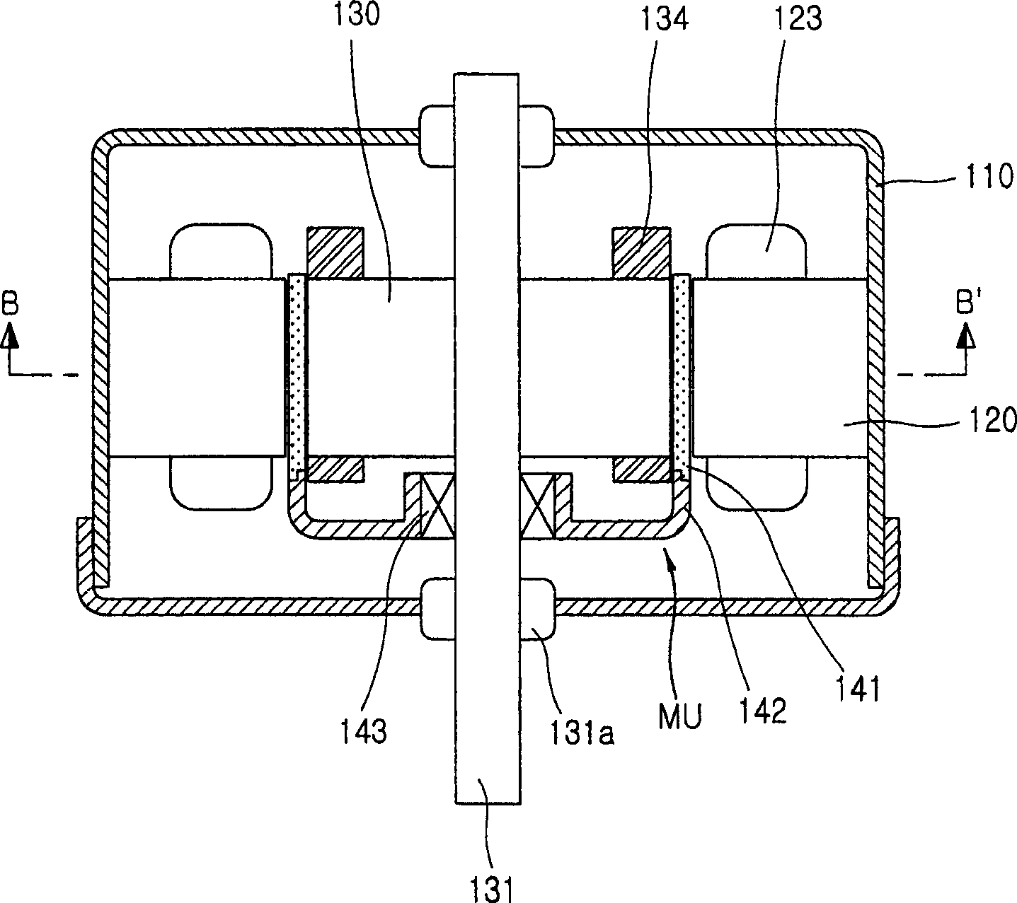
[0033] image 3 is a longitudinal sectional view showing the inside of the single-phase induction motor according to the present invention. Figure 4 is along image 3 Sectional view of line B-B` in middle. Figure 5 is a partially cutaway perspective view showing a magnetic unit of a single-phase induction motor according to the present invention.

[0034] according to Figures 3 to 5 , the single-phase induction motor according to the present invention includes: a motor main body 110 as a casing; a stator 120 arranged along the inner peripheral surface of the main body 110; a rotor 130 rotatably arranged at the center of the stator 120; and the rotor 130 surrounds Rotate the rotating shaft 131 . In this case, the rotor 130 is designed to always be at a constant distance from the stator 120 .

[0035] A rotating sh...


PUM


Abstract

A single phase induction motor comprises: a stator installed at an inner circumferential surface of a motor housing, comprising a stator core on which a plurality of coils are wound; a rotor rotatably installed at a center of the stator and provided with a shaft at a center thereof; and a permanent magnetic unit in the air gap between stator and rotor and able to rotate around the shaft.

Description

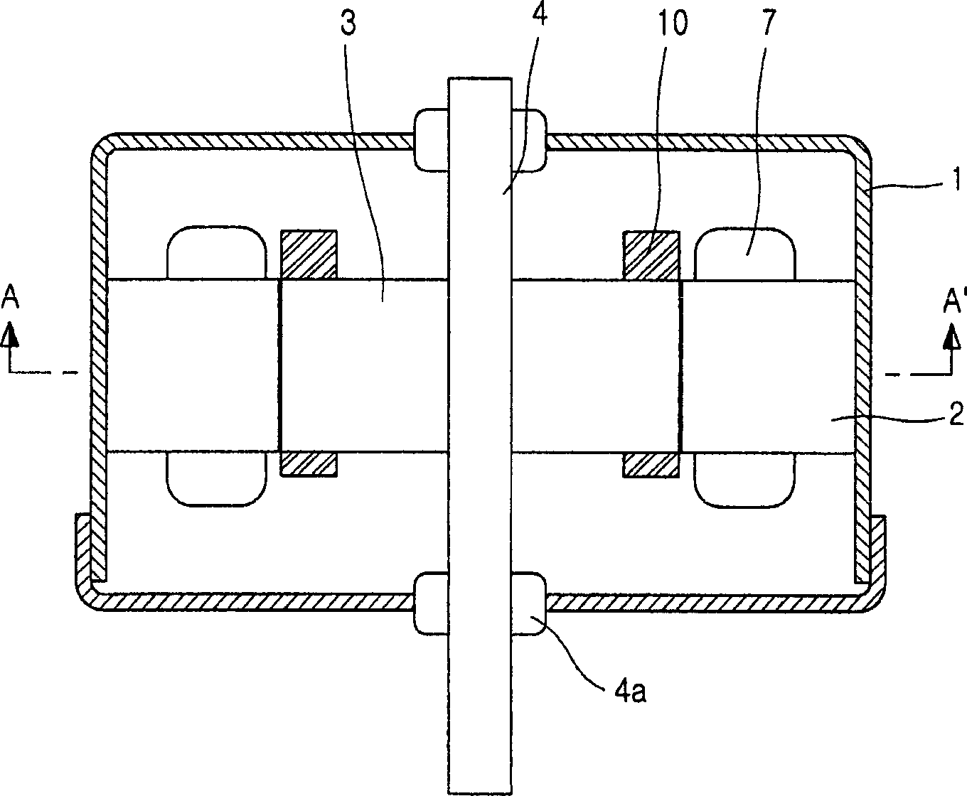
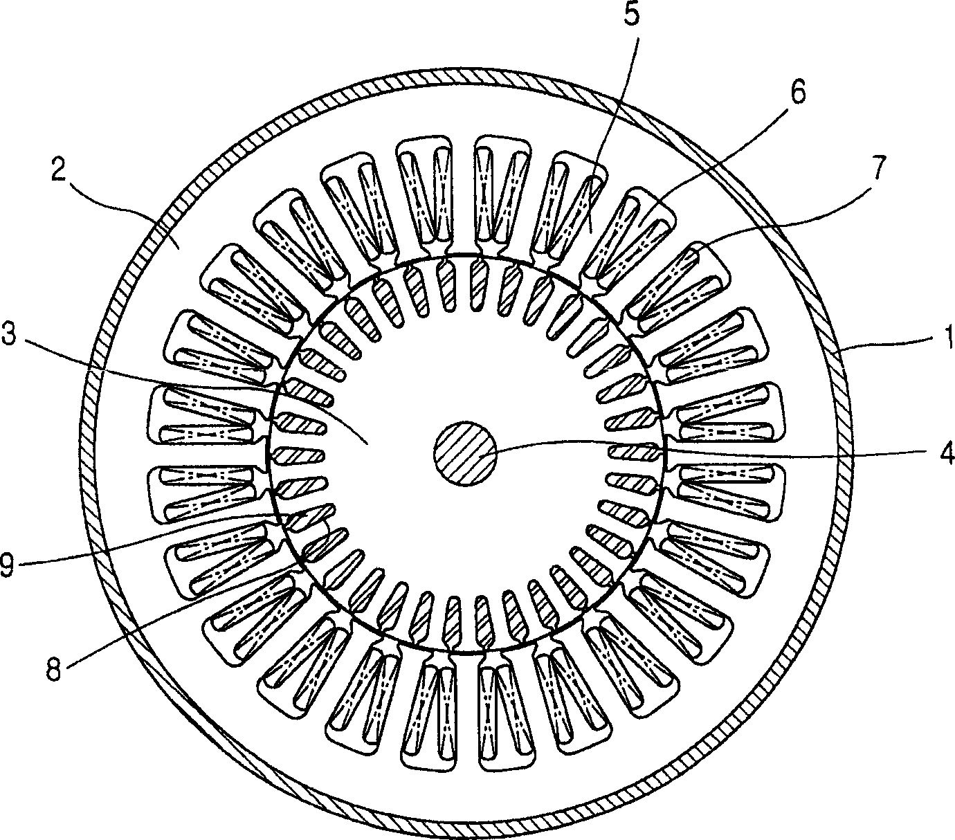
technical field [0001] The present invention relates to a motor, and in particular, to a single-phase induction motor that reduces consumed power and generated noise by installing a magnetic unit in a body of the induction motor. Background technique [0002] In general, an induction motor is an electric motor using alternating current without a rectifier, and one of a rotor and a stator thereof is connected to a power source and the other is operated by induction. [0003] figure 1 is a longitudinal sectional view showing the inside of a conventional single-phase induction motor, figure 2 yes figure 1 Sectional view along line A-A. [0004] see figure 1 and figure 2 , a conventional single-phase induction motor includes: a motor main body 1 as a housing; a stator 2 arranged along the inner peripheral surface of the main body 1; an alternating current squirrel-cage rotor 3 rotatably arranged at the center of the stator 2; and a rotor 3 Axis of rotation around which t...

Claims


Application Information

Patent Timeline
Patent Type & Authority Applications(China)
IPC IPC(8): H02K17/30H02K16/02H02K17/04H02K17/16H02K21/14
CPCH02K17/04H02K16/02H02K21/14
Inventor 韩承道申铉定安埈澔
Owner LG ELECTRONICS INC
Learn More