Bias control loop of PA chip

A technology of bias control and control circuit, applied in the direction of control/adjustment system, adjustment of electrical variables, instruments, etc., can solve the problems of reducing control accuracy, increasing circuit cost, voltage or current error and loss, and reducing circuit cost. , the effect of reducing current loss and simplifying the structure

CN113900471AActive Publication Date: 2022-01-07深圳市时代速信科技有限公司
8 Cites 0 Cited by

Patent Information

Authority / Receiving Office
CN · China
Patent Type
Applications(China)
Current Assignee / Owner
Publication Date
2022-01-07

Smart Images

  • Figure 1
    Figure 1
  • Figure 2
    Figure 2
  • Figure 3
    Figure 3
Patent Text Reader

Abstract

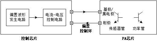
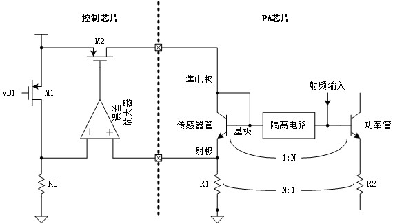
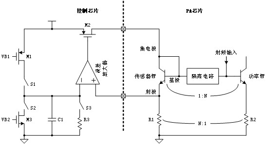
The invention discloses a bias control loop of a power amplifier (PA) chip. The bias control loop comprises a control chip and the PA chip, the control chip is provided with a bias waveform generation circuit and a current and voltage control circuit which are connected with each other, the PA chip is provided with a sensor tube, and a base electrode end and a collector electrode end of the sensor tube are connected; and the current and voltage control circuit is respectively connected with the emitter end of the sensor tube and the connecting end of the base end and the collector end of the sensor tube. According to the invention, emitter voltage of the sensor tube on the PA chip can be collected, correction waveform and feedback waveform operation is carried out on the voltage, and finally the voltage is converted into bias current and directly transmitted to a collector and a base of the sensor tube, so that a simple closed-loop control circuit is formed, the structure of the control circuit is simplified, and the circuit cost is reduced. And moreover, the whole control process only needs to carry out voltage and current conversion once, so that the current loss caused by conversion can be reduced, and the control precision is improved.
Need to check novelty before this filing date? Find Prior Art

Description

technical field

[0001] The present invention relates to the technical field of control circuits, in particular to a bias control loop of a PA chip. Background technique

[0002] With the development of WIFI technology, its throughput continues to increase, and in WIFI FEM, GaAs technology is generally used to achieve power amplification to achieve sufficient linearity and output power. However, the output power of the GaAs power amplifier is related to parameters such as the current gain of the power amplifier, and these parameters are related to temperature. In order to make the output power of the power amplifier stable quickly, it is generally necessary to control the current of the power amplifier.

[0003] In order to accurately control the bias current of the power amplifier from power-on to stabilization, the current commonly used control method is to use a closed-loop control circuit. The circuit principle is to use a small-sized triode as a temperature sensor. The ...

Examples

Embodiment Construction

[0038] The following will clearly and completely describe the technical solutions in the embodiments of the present invention with reference to the accompanying drawings in the embodiments of the present invention. Obviously, the described embodiments are only some, not all, embodiments of the present invention. Based on the embodiments of the present invention, all other embodiments obtained by persons of ordinary skill in the art without creative efforts fall within the protection scope of the present invention.

[0039] The control circuit has the following technical problems: the method of forming feedback through the collector and the base, generally samples the collector current of the sensor, and feeds back a suitable voltage to the triode to drive the base of the triode, sometimes in order to cover the characteristics of the PA, It is also necessary to add a suitable current compensation waveform, which makes the circuit very complicated, and it is difficult to directly...