Connecter of refrigerant pipeline

A technology for connecting devices and refrigerants, used in flange connections, pipes/pipe joints/fittings, pipes, etc., can solve the problem of device assembly or disassembly, and achieve a high degree of sealing.

Active Publication Date: 2004-09-22
KANDITECKUNLE
View PDF1 Cites 6 Cited by
  • Summary
  • Abstract
  • Description
  • Claims
  • Application Information

AI Technical Summary

Problems solved by technology

[0003] The disadvantage of this connecting device is that if only a limited space is available for this, the assembly or disassembly of the device is very labor-intensive

Method used


Image

  • Connecter of refrigerant pipeline
  • Connecter of refrigerant pipeline
  • Connecter of refrigerant pipeline

Examples


Embodiment Construction

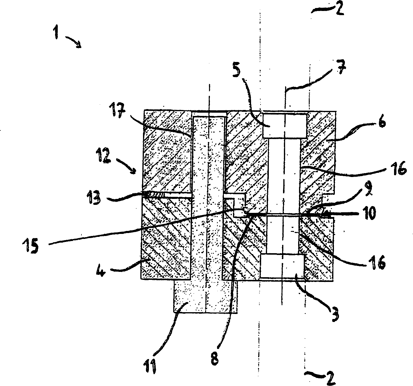
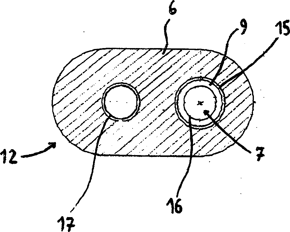
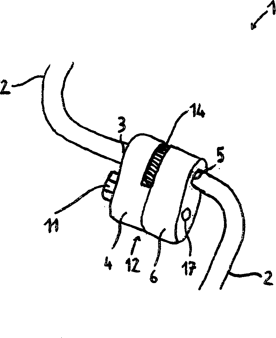
[0017] figure 1 The shown connecting device 1 for the refrigerant pipeline 2 comprises a first coupling part 4 and a second coupling part 6, the first coupling part is sealingly connected with a first pipe end 3; The second coupling part is connected in a sealing manner to a second pipe end 5 . The connection between the connecting part 4 , 6 and the pipe end 3 , 5 is non-detachable and materially bonded, wherein the connecting part 4 , 6 has a hole 16 into which the pipe end 3 , 5 is inserted. The holes 16 simultaneously function as connecting channels. The two coupling parts 4 and 5 are screwed together by means of a single screw 11, wherein the hole 17 in the coupling part 6 has an internal thread. By screwing, the pipe ends 3 are connected to one another centrally along an axis 7 via bores 16 . Furthermore, the two coupling parts 4 and 6 each have a radially extending sealing surface 8 and 9 on the side facing the other coupling part 6 and 4 , while a sealing ring 10 is...


PUM


Abstract

The connecting arrangement (1) for coolant pipes (2) has a first (4) and second (6) connecting piece joined together by a single screw (11) offset to the side of the sealing faces (8,9). Positioned away from the screw and on the side (12) furthest from the sealing faces is a non-compressible preformed component (13) acting as a spacer, and constructed in such a way that when the connecting pieces are screwed together a lever action ensues which results in a uniform compression of a sealing ring (10) between the sealing faces of the connecting pieces.

Description

technical field [0001] The invention relates to a connection device for refrigerant pipes according to the preamble of claim 1 . Background technique [0002] DE29908541U1 discloses a connection device for refrigerant pipes, in particular for automotive air conditioners working with CO2, in which the pipe ends of the two refrigerant pipes each have a joint . The two coupling parts each have a radially extending sealing surface on the side facing the other coupling part, wherein a metal flat ring with a bead is inserted between the sealing surfaces. Metal flat rings with a bead are pressed together by tightening the two joints together and create the necessary axial seal of the connection. The screwing of the two coupling parts together is achieved by providing one coupling part with an external thread onto which a union nut connected to the second coupling part is screwed. Alternatively, the joints are connected to one another by means of screws, wherein the screws are ar...

Claims


Application Information

Patent Timeline
Patent Type & Authority Applications(China)
IPC IPC(8): F16L23/16B60H1/32F16L41/08F25B1/00F25B41/00
CPCB60H1/00571F16L23/20F25B2309/061F16L41/086
Inventor A·维尔德穆斯M·埃斯曼
Owner KANDITECKUNLE
Why Eureka
Try Eureka