Rotary gyroscope

A technology of gyroscopes and components, applied in the field of gyroscopes, can solve problems such as slowing down of sensing motion, difficulty in matching drive and sensing frequencies, and complicated manufacturing processes

Inactive Publication Date: 2004-09-22
SAMSUNG ELECTRONICS CO LTD
View PDF1 Cites 5 Cited by
  • Summary
  • Abstract
  • Description
  • Claims
  • Application Information

AI Technical Summary

Problems solved by technology

However, these other conventional miniature gyroscopes present some varying problems
For example, these conventional miniature gyroscopes may have one or more of the following problems: due to the coupling of the motion of the driving unit including the driving object and the sensing unit including the sensing object, it is difficult to match the driving and sensing frequencies, and the sensing object or Sticking between the sending unit and sensing electrodes, performance degradation due to weak buoyancy, slowed sensing motion, sensing pattern deformation or relatively complex fabrication process

Method used


Image

  • Rotary gyroscope
  • Rotary gyroscope
  • Rotary gyroscope

Examples


Embodiment Construction

[0036] The entire contents of Korean Patent Application No. 2003-14106, filed March 6, 2003, entitled "Rotary Gyroscope" are incorporated by reference.

[0037] The present invention will now be described more fully hereinafter with reference to the accompanying drawings showing preferred embodiments of the invention. However, this invention may be embodied in different forms and should not be construed as limited to only the embodiments set forth herein. Rather, these embodiments are provided so that this disclosure will be thorough and complete, and will fully convey the scope of the invention to those skilled in the art. The same numeral of a reference number designates the same element throughout.

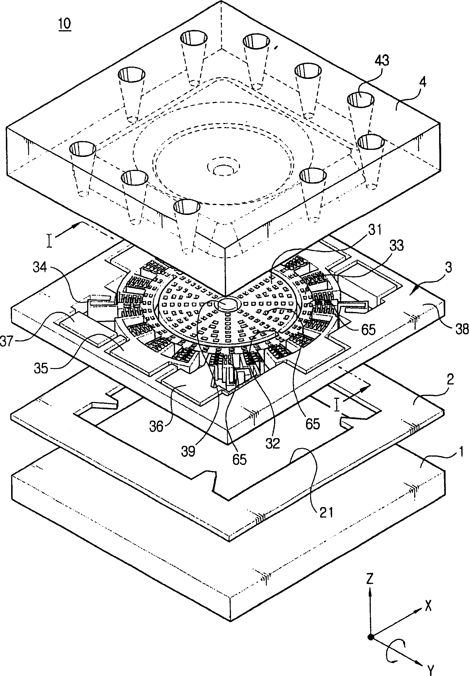
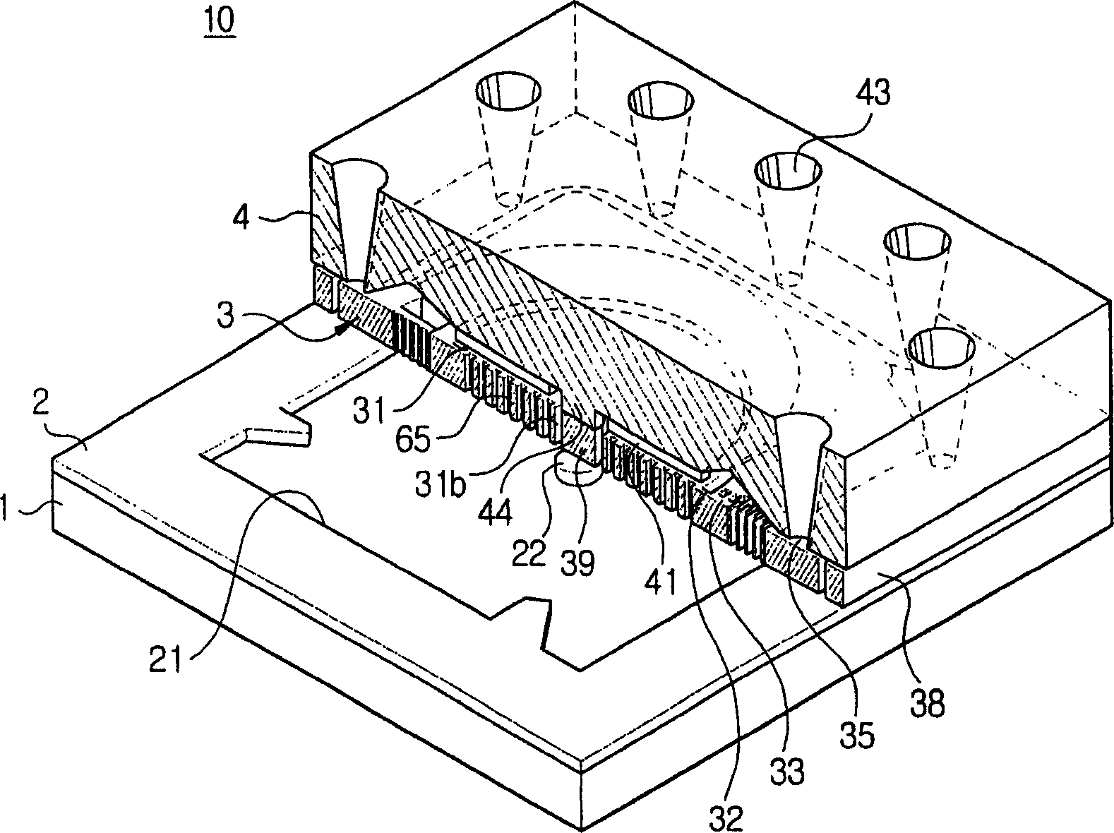
[0038] Figure 1A with 1B An exploded perspective view and a partially cutaway perspective view are shown of a rotating gyroscope 10 according to a preferred embodiment of the present invention.

[0039] refer to Figure 1A with 1B , the rotating gyroscope 10 includes a bas...


PUM


Abstract

A rotary gyroscope includes a base plate, an intermediate structure, including a driven element floating over the base plate as supported by a driving supporter radially extending therefrom, the driven element performing an oscillating motion with respect to a first axis, which is vertical to a center plane thereof, a driving electrode driving the driven element , and a sensing element disposed in the driven element and connected to the driven element by a sensing connector to oscillate together with the driven element and concurrently to perform a sensing motion with respect to a third axis, which is vertical to the first axis and any second axis, which is parallel to a center plane, due to a Coriolis force when an angular velocity is inputted from the second axis, and a cover covering the intermediate structure and having a sensing electrode to detect the sensing motion of the sensing element.

Description

technical field [0001] The present invention relates to a gyroscope for detecting angular velocity using rotational resonant motion of an object moving at a regular angle. In particular, the present invention relates to a rotating gyroscope capable of sensing multiple angular velocities corresponding to multiple axes in a plane. Background technique [0002] Generally, the gyroscope detects the rotational angular velocity by converting the displacement of the object caused by the Earth's rotation deflection force (Coriolis force) into a change in capacitance, based on the following principle, that is, when an object oscillating or rotating in the direction of the first axis is moved from the vertical When a force rotating at a constant angular velocity is applied in the direction of the first axis and the second axis, the earth rotation deflection force acts on the object in the direction of the third axis perpendicular to the first axis and the second axis. [0003] Such g...

Claims


Application Information

Patent Timeline
Patent Type & Authority Applications(China)
IPC IPC(8): G01C19/02G01C19/56G01C19/5642G01C19/5712
CPCG01C19/02G01C19/5642
Inventor 郑喜文宋仁燮姜锡镇
Owner SAMSUNG ELECTRONICS CO LTD
Why Eureka
Try Eureka